
Power generating system

a power generation system and power generation technology, applied in the direction of electric generator control, active/predictive/anticipative control, machines/engines, etc., can solve the problems of cost effectiveness and further deployment difficulties, and achieve the effect of stable power supply

Inactive Publication Date: 2010-09-28
MITSUBISHI HEAVY IND LTD
View PDF15 Cites 34 Cited by
  • Summary
  • Abstract
  • Description
  • Claims
  • Application Information

AI Technical Summary

Benefits of technology

[0007]The present invention has been conceived to solve the above-described problems, and an object thereof is to provide a power generating system capable of realizing high-quality and stable power supply, without using expensive equipment such as an electrical power storage device.
[0022]The power generating system and the variable-speed wind power generator according to the present invention provides an advantage in that it is possible to realize high-quality and stable power supply without using expensive equipment such as an electrical power storage device.

Problems solved by technology

However, since the electrical power storage device mentioned above is expensive, it is less feasible in terms of cost effectiveness, thus making its further deployment difficult.

Method used


Image

  • Power generating system
  • Power generating system
  • Power generating system

Examples


first embodiment

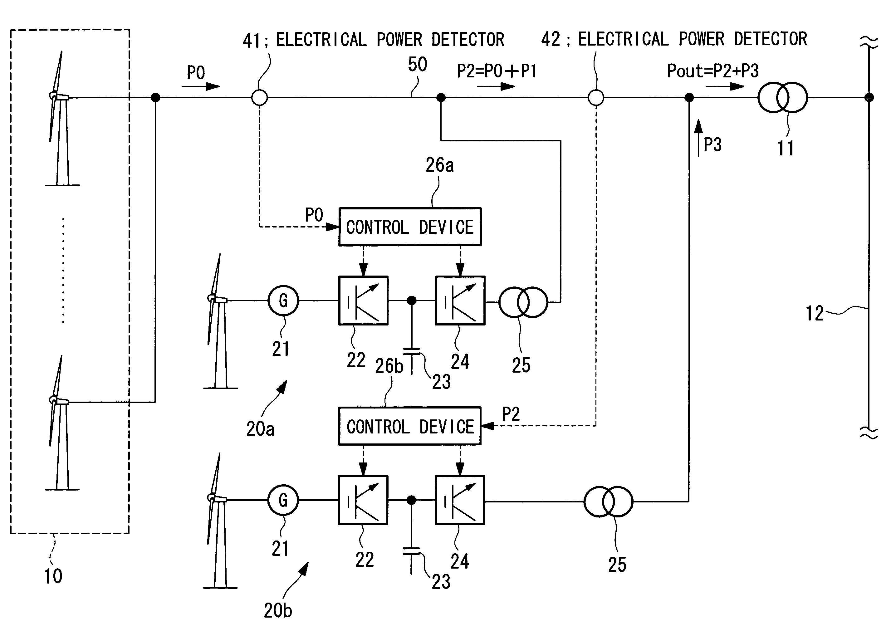
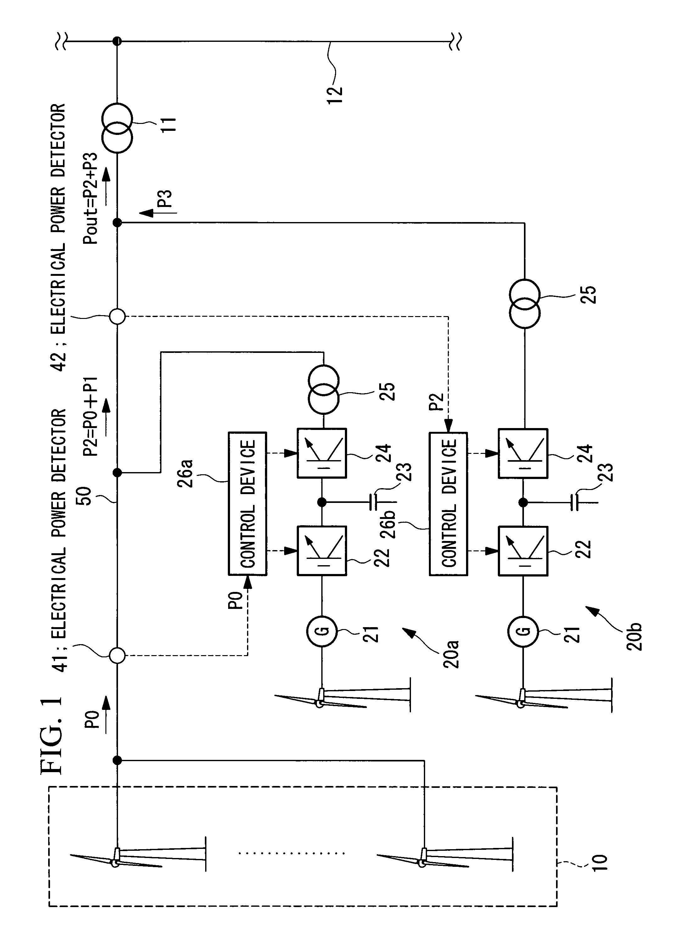
[0030]FIG. 1 is a block diagram showing, in outline, the configuration of a power generating system according to the present invention.

[0031]As shown in FIG. 1, the power generating system according to this embodiment includes a power generator 10 having a plurality of wind power generators that generate electrical power using natural energy. In this case, each of the wind power generators included in the power generator 10 may be fixed-speed wind power generators, variable-speed wind power generators, or a combination thereof.

[0032]The power generator 10 is connected to an electrical power system 12 via an electrical power converter 11. A plurality of variable-speed wind power generators 20a and 20b are connected between the power generator 10 and the electrical power converter 11. These variable-speed wind power generators 20a and 20b output power to correct for a drop in the output of the power generator 10 (for example, a drop in output power). The number thereof is determined, ...

second embodiment

[0057]Next, the present invention will be described with reference to FIG. 4.

[0058]A power generating system of this embodiment differs from the power generating system according to the first embodiment in that a central management device 60 is provided for centrally controlling each of the variable-speed wind power generators 20a and 20b, and each variable-speed wind power generator 20a and 20b controls the output based on commands from the central management device 60.

[0059]In the power generating system of this embodiment, a description of the features common to the first embodiment is omitted, and only differences from the first embodiment will be described below.

[0060]The output power P0 from the power generator 10 is input to the central management device 60 from the electrical power detector 41, and output powers P4 and P5 from the generators 21 provided in the variable-speed wind power generators 20a and 20b are input to the central management device 60.

[0061]The central man...


PUM


Abstract

Provided is a power generator, including a plurality of wind power generators generating electrical power using wind power energy, and variable-speed wind power generators (20a, 20b) connected between the power generator and an electrical power system. The variable-speed wind power generators (20a, 20b) equalize an output of the entire power generating system by outputting power for correcting for a drop in output of the power generator.

Description

CROSS REFERENCE TO RELATED APPLICATIONS[0001]The present Application is based on International Application No. PCT / JP2006 / 302707, filed Feb. 16, 2006 which in turn corresponds to Japan Application No. 2005-041012, filed Feb. 17, 2005 and priority is hereby claimed under 35 USC §119 based on these applications. Each of these applications are hereby incorporated by reference in their entirety into the present application.TECHNICAL FIELD[0002]The present invention relates to power generating systems combining power generators that generate electrical power using natural energy and variable-speed wind power generators, and more particularly, relates to a power generating system outputting equalized electrical power by virtue of a variable-speed wind power generator outputting power for correcting a drop in output of the power generator.BACKGROUND ART[0003]In a power generator such as a wind power generator or a solar power generator using natural energy, since the output is highly influ...

Claims


Application Information

Patent Timeline
Patent Type & Authority Patents(United States)
IPC IPC(8): F03D9/00
CPCF03D7/0276F03D7/028F03D7/048Y02E10/725F05B2270/404Y02E10/723F05B2240/96Y02E10/72Y02E10/76F03D7/04H02P9/00F03D9/00
Inventor ARINAGA, SHINJI
Owner MITSUBISHI HEAVY IND LTD
Learn More