Signal, interference and noise power measurement

a technology of interference and power measurement, applied in the direction of line-fault/interference reduction, transmission monitoring, amplifiers with transit-time effect, etc., can solve the problems of preventing its use, distorting a received signal, interfering at their boundaries, etc., and achieve high accuracy and consistent

Active Publication Date: 2010-10-26
DIRECTV LLC
View PDF283 Cites 13 Cited by
  • Summary
  • Abstract
  • Description
  • Claims
  • Application Information

AI Technical Summary

Benefits of technology

[0012]This invention provides a systematic and unified approach to separate the carrier, interference and noise from a received signal for separate power measurements. The result is a consistent and highly accurate estimate of key measurements of signal quality.

Problems solved by technology

For example, satellite systems employing spotbeams with substantially similar transmission frequencies over adjacent coverage areas may interfere at their boundaries.
Noise and interference, however, may distort a received signal and prevent its use even if the carrier power is otherwise sufficient.

Method used


Image

  • Signal, interference and noise power measurement
  • Signal, interference and noise power measurement
  • Signal, interference and noise power measurement

Examples


Embodiment Construction

[0025]In the following description, reference is made to the accompanying drawings which form a part hereof, and which show, by way of illustration, several embodiments of the present invention. It is understood that other embodiments may be utilized and structural changes may be made without departing from the scope of the present invention.

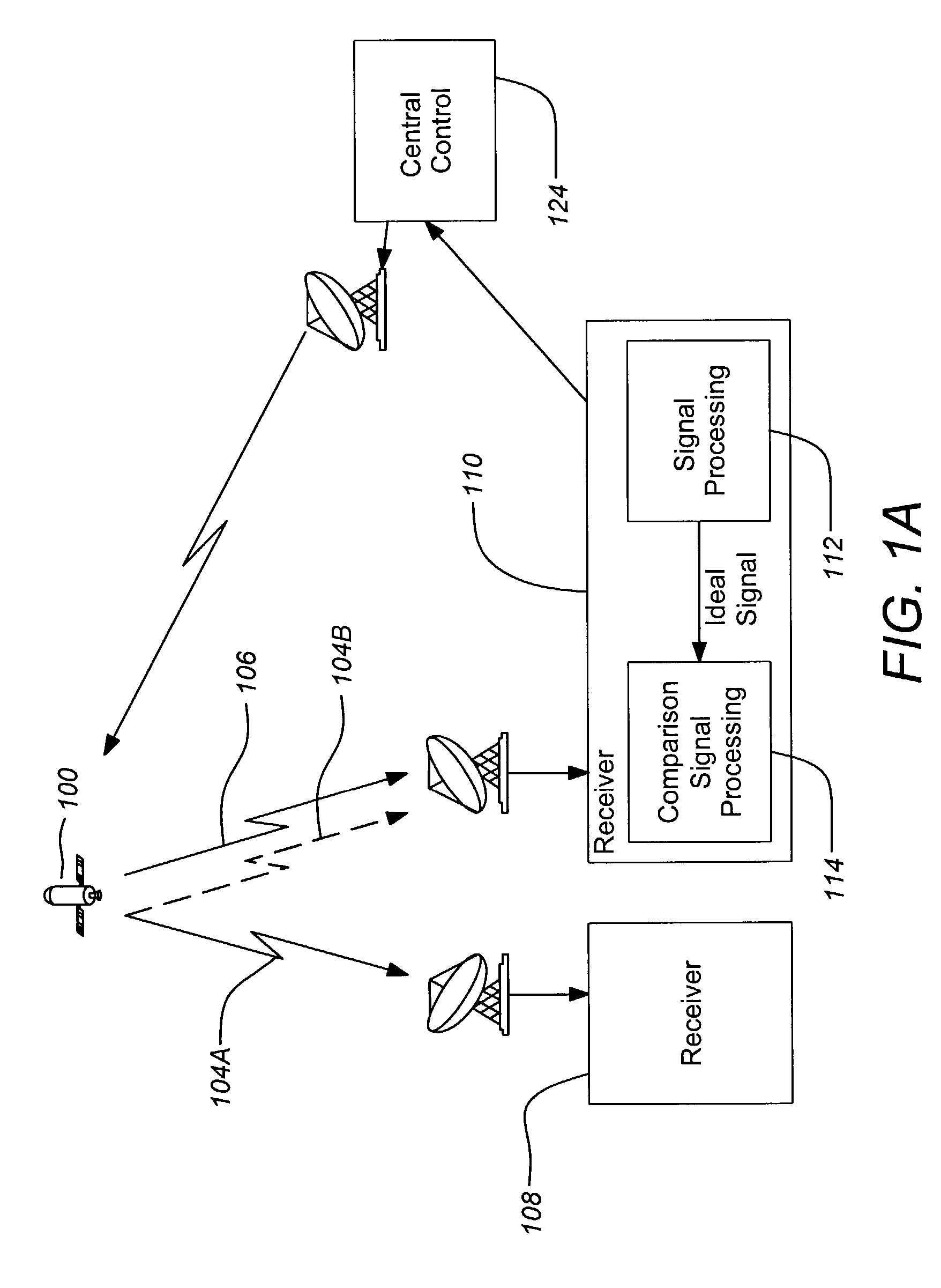
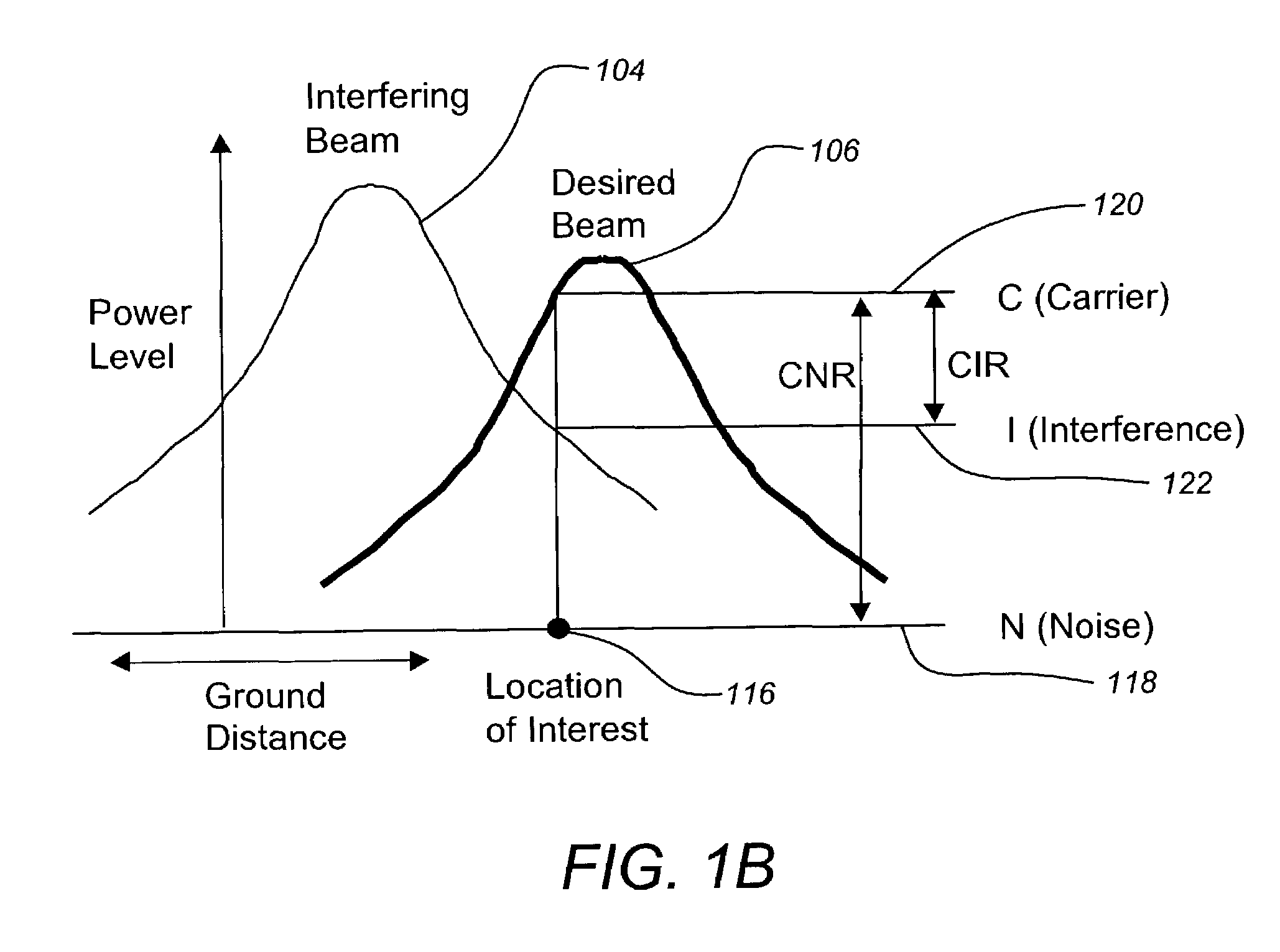
[0026]FIGS. 1A-1B illustrate a typical system and interference scenario of the present invention. FIG. 1A depicts a typical system of the present invention. One or more satellites 100 transmit signals 104, 106 to receivers 108, 110 in different geographical regions. The signals 104, 106 may have similar carrier frequencies and carry different information. Because the signals 104, 106 employ very similar carrier frequencies there is a potential for them to interfere. Interference is principally minimized through a geographic separation of the receivers 108, 110, i.e. through spatial diversity. Similarly, the signals may be separated based on the ...


PUM


Abstract

Systems and methods are presented for measuring power levels of primary and interfering signals as well as noise, particularly for satellite transmitted signals. A typical method comprises the steps of receiving a signal comprising a primary signal, an interference signal and noise, demodulating the primary signal to remove a carrier frequency, decoding the primary signal to obtain symbols, estimating a power level of the primary signal based upon the demodulated and decoded primary signal. Additionally, an ideal primary signal can be generated from the carrier power and frequency and the symbols and subtracted from the received signal to produce the noise and interference signal. The noise and interference power is then estimated from the noise and interference signal.

Description

CROSS-REFERENCE TO RELATED APPLICATIONS[0001]This is a continuation-in-part application and claims the benefit under 35 U.S.C. Section 120 of the following co-pending and commonly-assigned U.S. utility patent application, which is incorporated by reference herein:[0002]Utility application Ser. No. 09 / 844,401, filed Apr. 27, 2001, by Ernest C. Chen, entitled “LAYERED MODULATION FOR DIGITAL SIGNALS,”.BACKGROUND OF THE INVENTION[0003]1. Field of the Invention[0004]The present invention relates generally to systems and methods for monitoring signal qualities of a transmitted signal based on measuring the received signal, and particularly for measuring carrier, interference and noise power in a satellite signal.[0005]2. Description of the Related Art[0006]In systems employing transmitted signals it is often necessary to estimate the signal quality to obtain an indication of the system performance. There is also a need to monitor frequency reuse across a multiple coverage areas. For examp...

Claims


Application Information

Patent Timeline
Patent Type & Authority Patents(United States)
IPC IPC(8): H03D1/04H03F1/32H03F3/58H04B7/185H04B17/00H04L27/36
CPCH04B7/1851H04B7/18515H04B7/18526H04L1/20H04L1/206H04B17/318H04L27/183H04L27/227H04L27/366H04L1/208H04L2027/0061
Inventor CHEN, ERNEST C.TRAN, CHINH
Owner DIRECTV LLC
Why Eureka
Try Eureka