Mortise lock for ordinary door and panic door

a technology of mortise locks and panic doors, which is applied in the direction of keyhole guards, mechanical control devices, instruments, etc., can solve the problem of not allowing the pivotal movement of the driving rod, and achieve the effect of facilitating the description of the invention

Active Publication Date: 2010-11-23
I TEK METAL MFG
View PDF11 Cites 22 Cited by
  • Summary
  • Abstract
  • Description
  • Claims
  • Application Information

AI Technical Summary

Problems solved by technology

A locking plate is mounted in the case and movable between an upper, unlocking position allowing pivotal movement of the driving rod and a lower, locking position not allowing pivotal movement of the second lug of the driving rod and thus not allowing pivotal movement of the driving rod.

Method used


Image

  • Mortise lock for ordinary door and panic door
  • Mortise lock for ordinary door and panic door
  • Mortise lock for ordinary door and panic door

Examples


Embodiment Construction

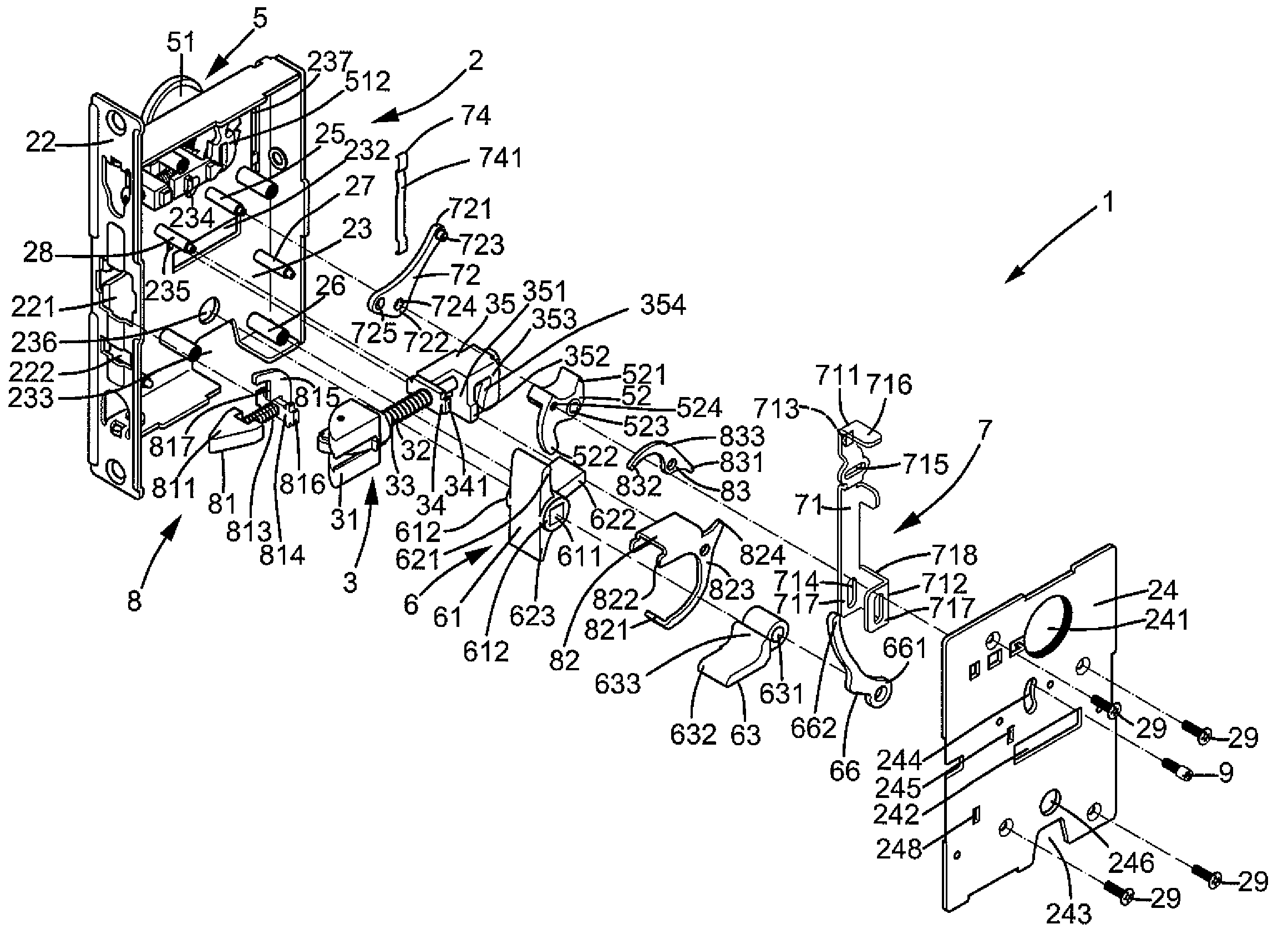
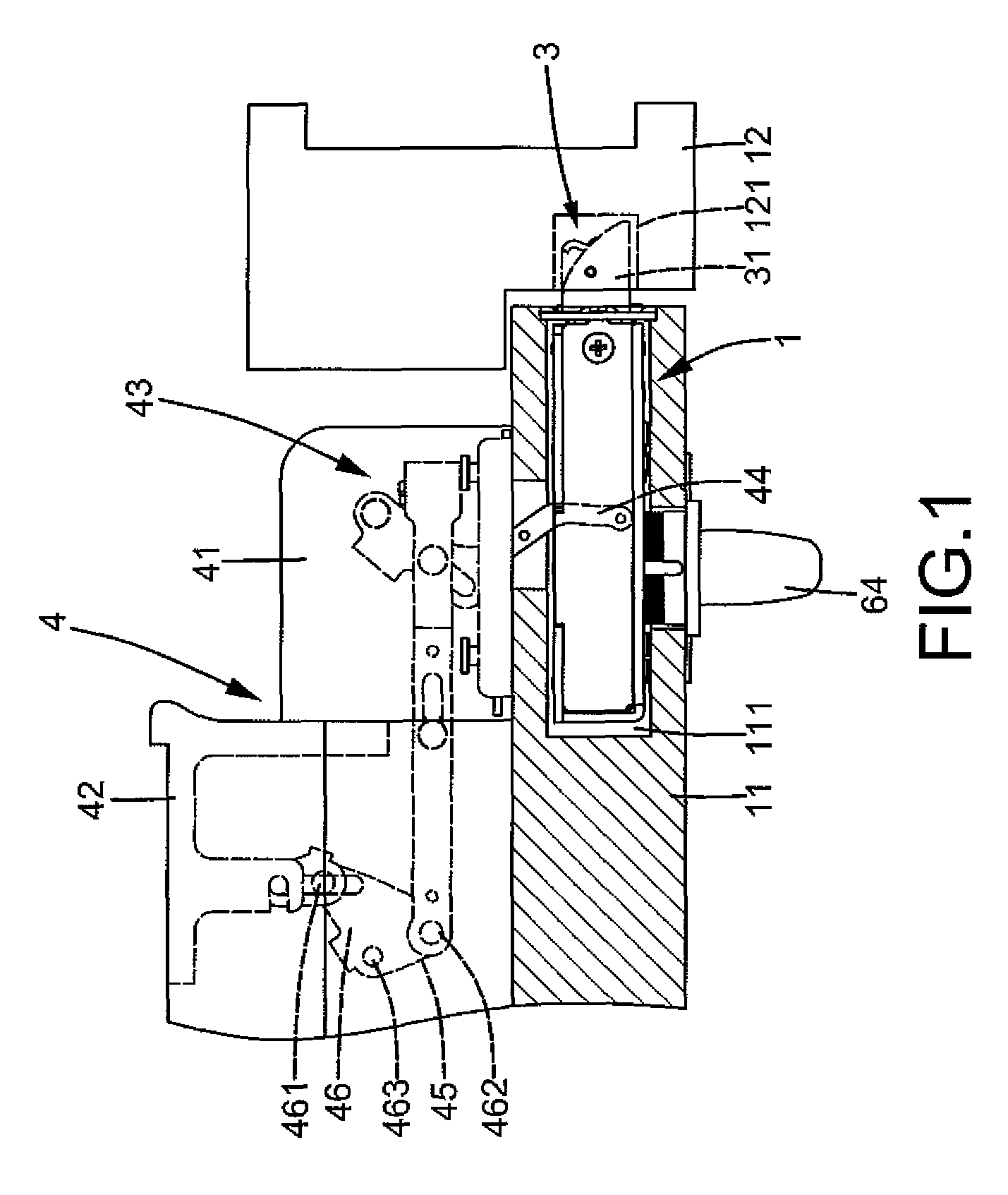
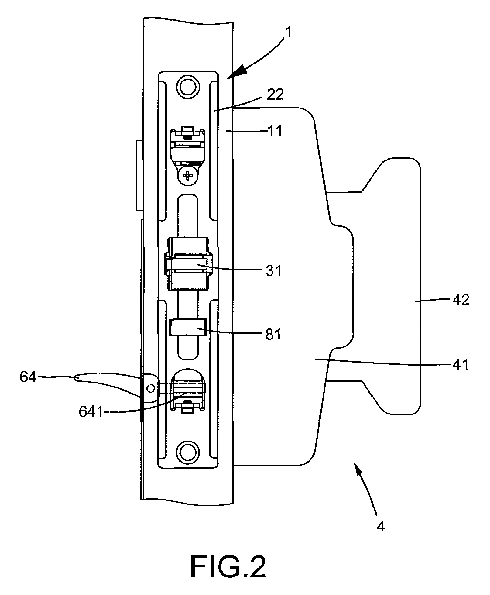
[0026]A mortise lock according to the preferred teachings of the present invention is shown in the drawings and generally designated 1. According to the preferred form shown, mortise lock 1 is mounted in a compartment 111 in an edge of a door 11. Mortise lock 1 includes a substantially parallelepiped-shaped case 2 including an outer end face 21. A faceplate 22 is mounted to outer end face 21 and forms a part of case 2. Faceplate 22 includes first and second openings 221 and 222 spaced in a vertical direction. Case 2 further includes two sidewalls 23 and 24 spaced in a direction perpendicular to the vertical direction. According to the most preferred form shown, sidewall 24 is in the form of a lid removably mounted by screws 29 to a side of case 2 opposite to sidewall 23. Sidewalls 23 and 24 include aligned cylinder holes 231 and 241 in upper portions thereof, aligned slots 232 and 242 in intermediate portions thereof, and aligned notches 233 and 243 in lower ends thereof Slots 232 a...


PUM


Abstract

A mortise lock includes a case having first and second sidewalls. A follower plate is pivotably mounted in the case and actuatable by a key-operable cylinder to move a latch bolt from an extended position to a retracted position. A locking plate is moveable by the cylinder through transmission by a lever link between an unlocking position allowing movement of the latch bolt and a locking position not allowing movement of the latch bolt. The locking plate is active when a connecting member is slideably extended through a slot in the first sidewall and through an engaging hole of the lever link into another engaging hole in the follower. The locking plat is inactive when the connecting member is slideably extended through another slot in the second sidewall and engaged in the engaging hole of the follower and not engaged in the engaging hole of the lever link.

Description

BACKGROUND OF THE INVENTION[0001]The present invention relates to a mortise lock and, more particularly, to a mortise lock that can be utilized with both an ordinary door and a panic door.[0002]Mortise locks having complicated structure are generally utilized on ordinary doors to provide enhanced security as well as multiple functions. As an example, U.S. Pat. No. 7,377,140 issued May 27, 2008 discloses a mortise lock with a clutching function to allow free rotation of the outer handle when the lock is in a locked state. However, direct mounting of mortise locks on panic doors is not always readily achievable. Modification to mortise locks is required in most cases. Furthermore, mortise locks are relatively expensive than those more commonly utilized on panic doors with fewer functions.[0003]A need exists for an inexpensive mortise lock that can be utilized with both an ordinary door and a panic door.BRIEF SUMMARY OF THE INVENTION[0004]The present invention solves this need and othe...

Claims


Application Information

Patent Timeline
Patent Type & Authority Patents(United States)
IPC IPC(8): E05B55/06E05C1/12
CPCE05B13/004E05B55/00E05B55/12E05B63/0065E05B65/10E05B65/1086E05B65/1053Y10T70/5226Y10T70/5496Y10T70/5531Y10T70/5805Y10T70/5832Y10T292/0982Y10T292/59
Inventor TIEN, HUNG-JENHUANG, CHEN-WEI
Owner I TEK METAL MFG
Why Eureka
Try Eureka