Collection tank

a collection tank and tank body technology, applied in the field of vacuum tanks, can solve the problems that conventional digging and excavation methods such as shovels, powered excavators, post-hole diggers, etc., may be limited in their use in locating buried utilities, and cannot always be guaranteed

Active Publication Date: 2010-11-23
VERMEER MFG CO
View PDF8 Cites 56 Cited by
  • Summary
  • Abstract
  • Description
  • Claims
  • Application Information

AI Technical Summary

Problems solved by technology

Conventional digging and excavation methods such as shovels, post hole diggers, powered excavators, and backhoes may be limited in their use in locating buried utilities as they may tend to cut, break, or otherwise damage the lines during use.
While a vacuum seal may be created, it cannot always be guaranteed especially if the door is warped.

Method used


Image

  • Collection tank
  • Collection tank
  • Collection tank

Examples


Embodiment Construction

[0038]Reference will now be made in detail to presently preferred embodiments of the invention, one or more examples of which are illustrated in the accompanying drawings. Each example is provided by way of explanation of the invention, not limitation of the invention. In fact, it will be apparent to those skilled in the art that modifications and variations can be made in the present invention without departing from the scope and spirit thereof. For instance, features illustrated or described as part of one embodiment may be used on another embodiment to yield a still further embodiment. Thus, it is intended that the present invention covers such modifications and variations as come within the scope of the appended claims and their equivalents.

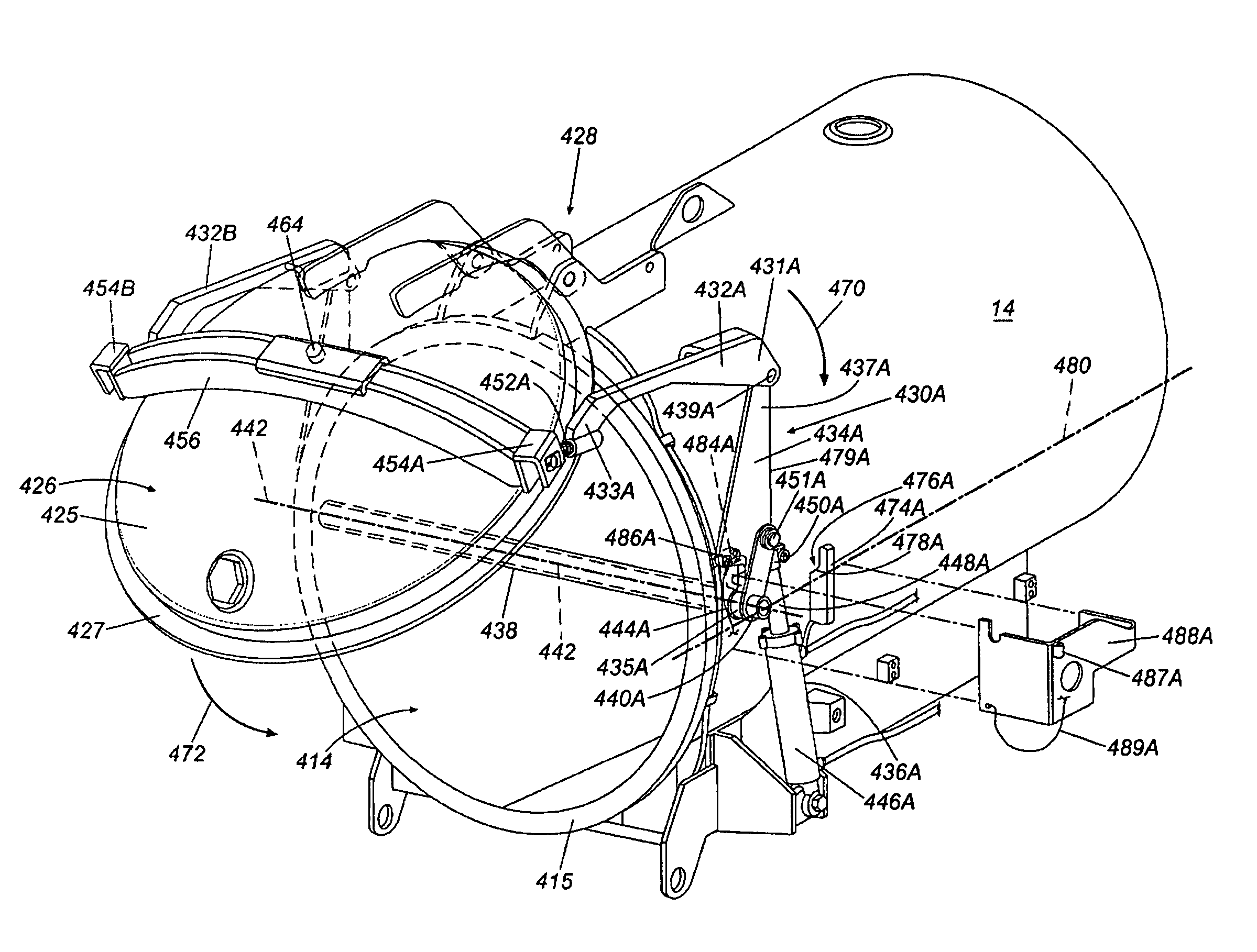
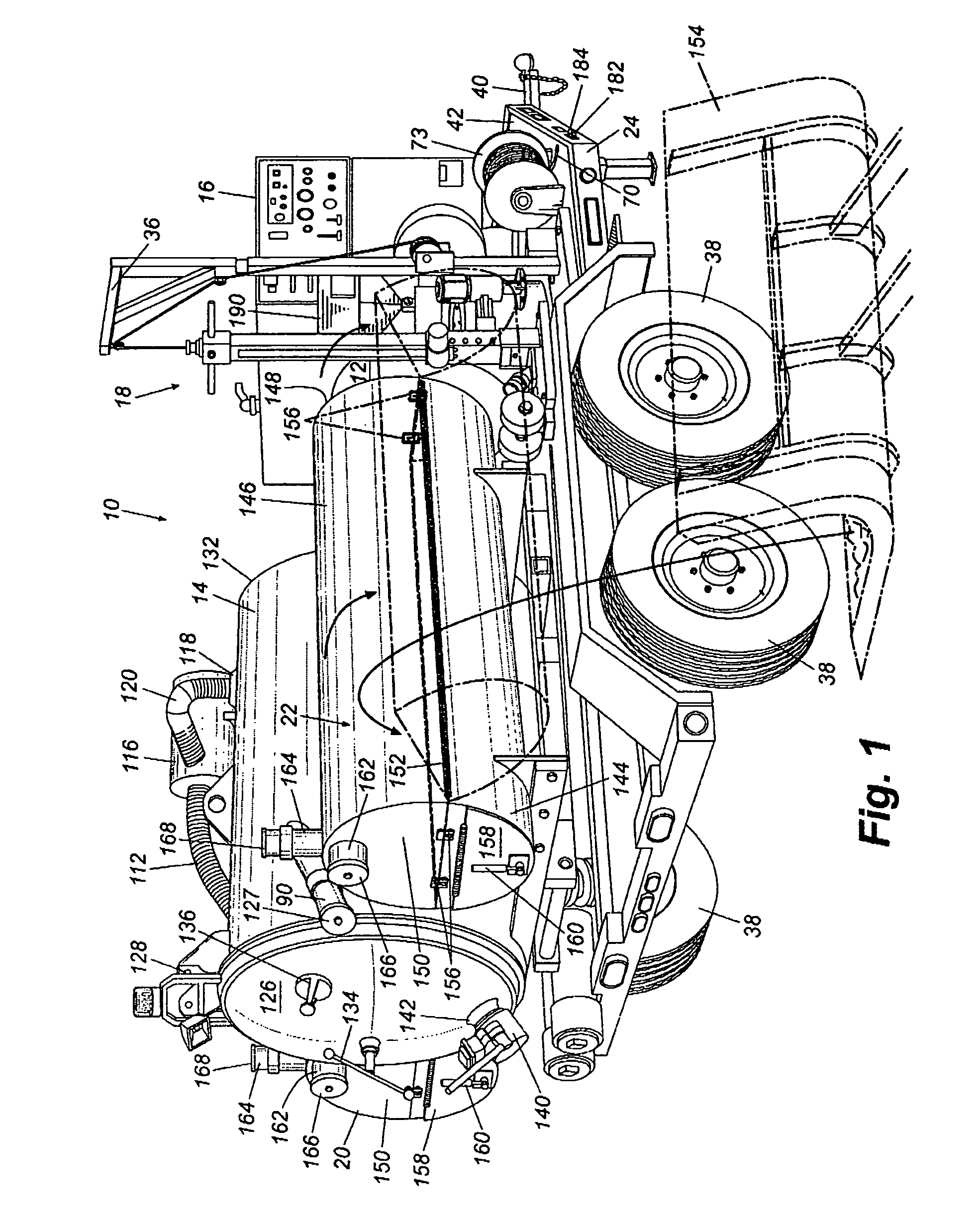
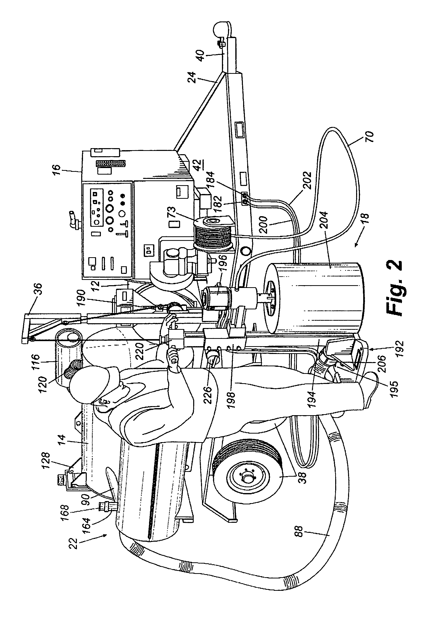
[0039]Referring to FIG. 1, a drilling and backfill system 10 generally includes a water reservoir tank 12, a collection tank 14, a motor 16, a drilling apparatus 18, and back fill reservoirs 20 and 22, all mounted on a mobile chassis 24, whic...


PUM


Abstract

A collection tank for use in a vacuum operated earth reduction system, the collection tank comprising a closed first end, an open second end defining a tank sealing flange and a body extending between the closed first end and the open second end. An internal chamber defined by the body, the closed first end and the open second end has a door coupled to the open second end and is configured to releasably seal the open second end. An automated door closer is coupled to a center of the door, wherein the automated door closer provides a closing force at the center of the door so that the closing force is equally distributed about a periphery of the door to seal the door against the tank sealing flange.

Description

FIELD OF THE INVENTION[0001]This invention relates generally to a reduction system for removing soil to expose underground utilities (such as electrical and cable services, water and sewage services, etc.), and more particularly to an improved vacuum tank for use with such system.BACKGROUND OF THE INVENTION[0002]With the increased use of underground utilities, it has become more critical to locate and verify the placement of buried utilities before installation of additional underground utilities or before other excavation or digging work is performed. Conventional digging and excavation methods such as shovels, post hole diggers, powered excavators, and backhoes may be limited in their use in locating buried utilities as they may tend to cut, break, or otherwise damage the lines during use.[0003]Devices have been previously developed to create holes in the ground to non-destructively expose underground utilities to view. One design uses high pressure air delivered through a tool to...

Claims


Application Information

Patent Timeline
Patent Type & Authority Patents(United States)
IPC IPC(8): B65D55/00
CPCB65D45/28E02F5/003E02F3/8816E02F3/925E02F3/8891E02F7/00B60P3/22B60P3/2245Y10T137/6855
Inventor MAYBURY, JR., CHARLES ROBERT
Owner VERMEER MFG CO
Why Eureka
Try Eureka