
Image reading apparatus correcting noise in image data

a reading apparatus and noise correction technology, applied in the field of image reading apparatuses, can solve the problem that the image data of the adjacent regions on the respective sides of the noise region is not always similar, and achieve the effect of accurate correction of nois

Inactive Publication Date: 2010-11-23
KONICA MINOLTA BUSINESS TECH INC
View PDF48 Cites 6 Cited by
  • Summary
  • Abstract
  • Description
  • Claims
  • Application Information

AI Technical Summary

Benefits of technology

[0010]The present invention has been made to overcome the above disadvantage and contemplates an image reading apparatus capable of accurately correcting noise generated in an image by dust existing on a platen.
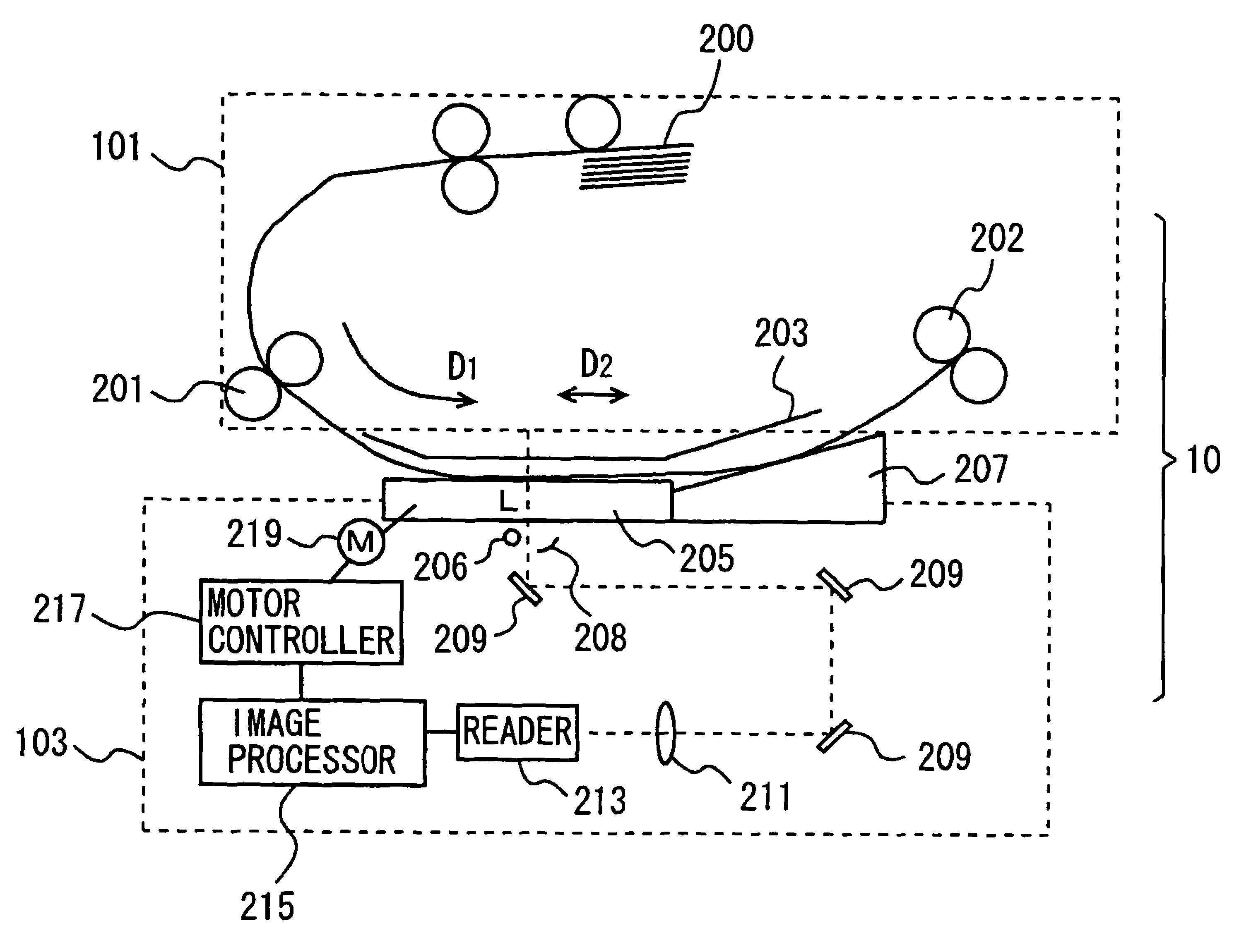
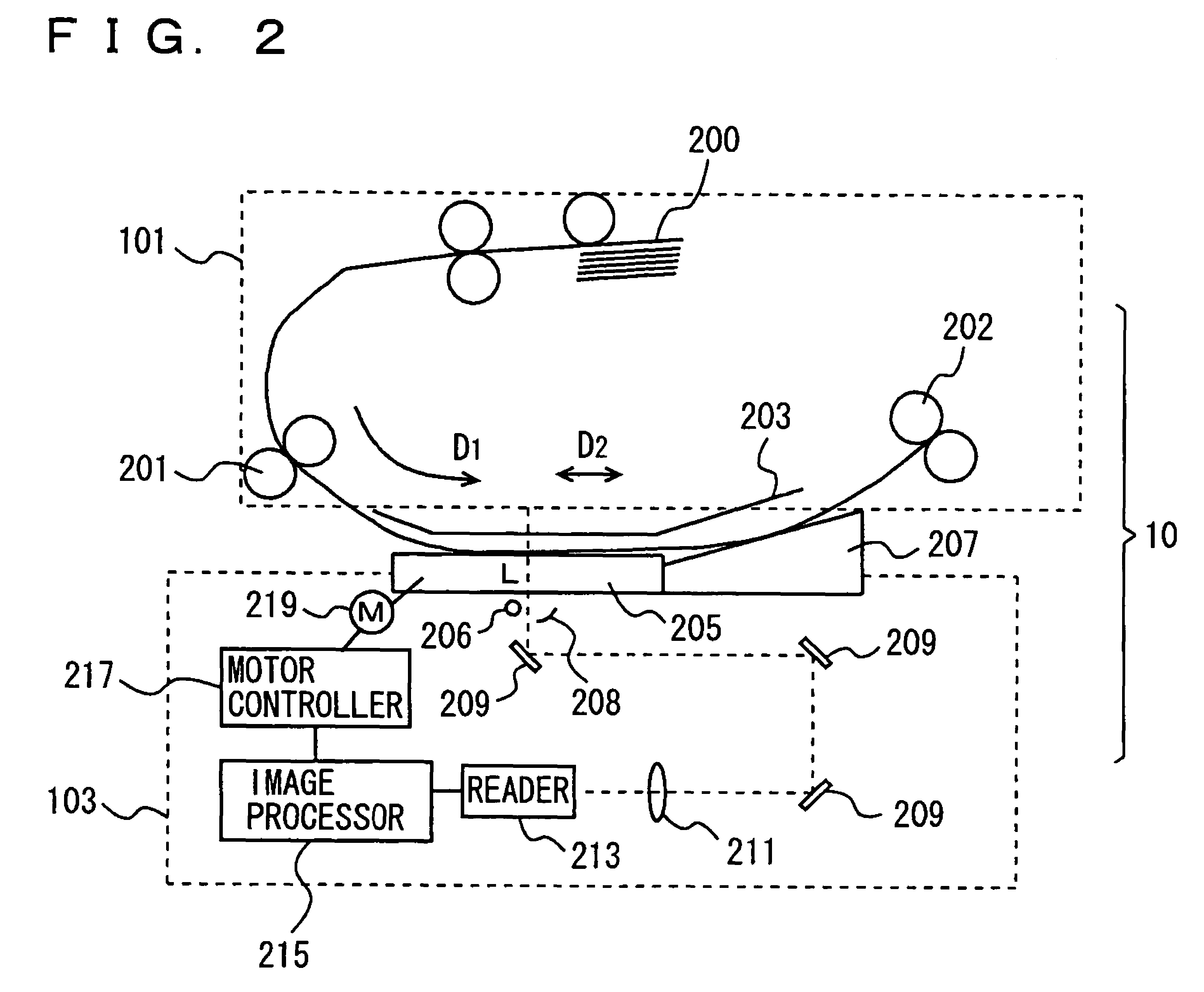
[0012]In accordance with the present invention the original is scanned in the sub scanning direction by a plurality of line sensors spaced in the sub scanning direction and between the original and the line sensors there is provided the platen moving at a rate relative to the line sensors, the rate being different from that of the original relative to the line sensors. When the platen has dust adhering thereon, the dust is read by the line sensors sequentially. As the platen is moved at a rate relative to the line sensors, the rate being different from that of the original relative to the line sensors, the dust on the platen is read by each line sensor at a different location of the original. The image reading apparatus detects a noise pixel based on a plurality of data output from the line sensors. From a search range that is selected from a plurality of search ranges defined with reference to the noise pixel, the reference pixel is extracted for correcting the noise pixel. Based on the value of the extracted reference pixel, the noise pixel is corrected. Since the search range from which the reference pixel for correcting the noise pixel is extracted is selected from a plurality of search ranges, a search range appropriate for an image on the original can be selected. The image reading apparatus can thus be provided that is capable of accurately correcting noise.

Problems solved by technology

However, the image data of the adjacent regions on respective sides of the noise region is not always similar to the image data of the noise region.

Method used


Image

  • Image reading apparatus correcting noise in image data
  • Image reading apparatus correcting noise in image data
  • Image reading apparatus correcting noise in image data

Examples


Embodiment Construction

[0036]Hereinafter reference will be made to the drawings to describe embodiments of the present invention. In the following description, like components are denoted by like reference characters and also identical in name and function.

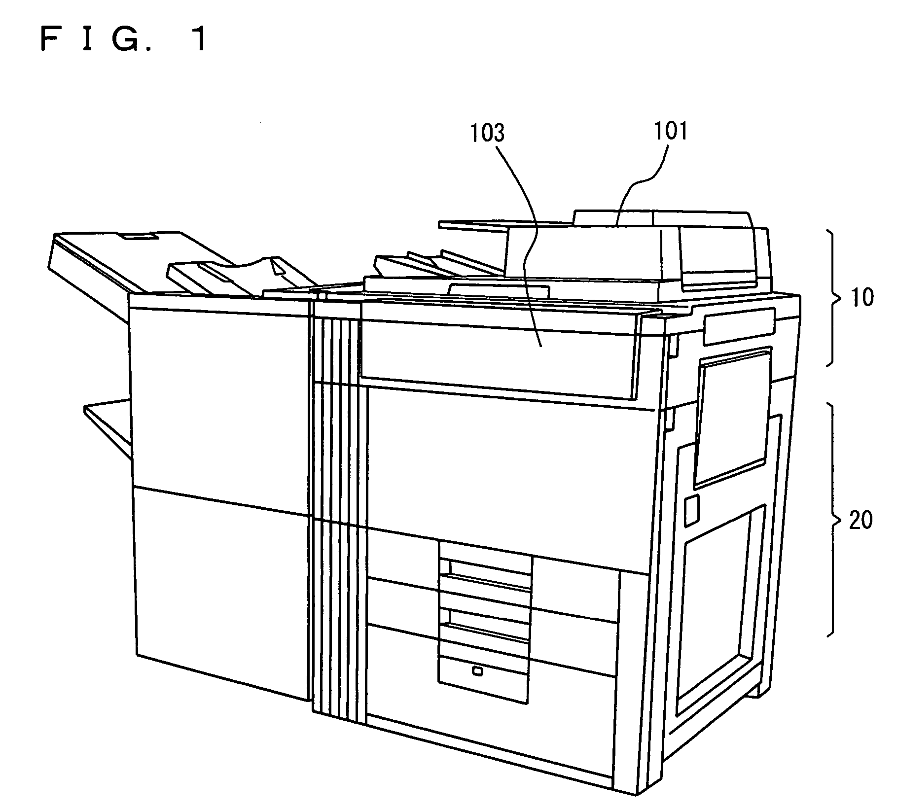
[0037]FIG. 1 is a perspective view of a multi-function peripheral (MFP) including an image reading apparatus in one embodiment of the present invention. With reference to the figure, the MFP includes an image reading apparatus 10 operative to read an original image, and an image forming apparatus 20 provided under image reading apparatus 10. The MFP forms an image read by image reading apparatus 10 on a sheet of paper or similar recording medium. Furthermore, the MFP includes a communications interface to connect with a facsimile device, a local area network (LAN), a public line or similar network.

[0038]FIG. 2 schematically shows an internal configuration of image reading apparatus 10. Image reading apparatus 10 includes an automatic document feeder (AD...


PUM


Abstract

An image reading apparatus includes, with the purpose of accurately correcting noise in an image due to dust on a platen, three line sensors spaced from each other in a sub scanning direction to scan an original in the sub scanning direction, a platen between the original and the three line sensors, a moving mechanism for moving the platen, a noise detection processor detecting a noise pixels from each of multiple data output from the three line sensors, a selector selecting one of a plurality of search ranges defined with reference to the noise pixel, and a corrector extracting a reference pixel for correcting the noise pixel from the selected search range to correct the noise pixel based on the value of the extracted reference pixel.

Description

[0001]This application is based on Japanese Patent Application No. 2004-286976 filed with the Japan Patent Office on Sep. 30, 2004, the entire content of which is hereby incorporated by reference.BACKGROUND OF THE INVENTION[0002]1. Field of the Invention[0003]The present invention relates generally to image reading apparatuses and particularly to image reading apparatuses reading an original while transporting it.[0004]2. Description of the Related Art[0005]Conventionally digital copiers and similar image reading apparatuses employ a technique referred to as so-called “reading an original while passing the original.” More specifically, an original is transported relative to a fixed line sensor in a sub scanning direction orthogonal to the line sensor as the original is read.[0006]Such image reading apparatus is provided with a transparent platen between the original and the line sensor to fix a position at which a transported original is read. The original reflects light which is in...

Claims


Application Information

Patent Timeline
Patent Type & Authority Patents(United States)
IPC IPC(8): H04N1/46H04N1/407G06K15/00
CPCH04N1/4097
Inventor SAKA, MASAAKIISHIGURO, KAZUHIRONABESHIMA, TAKAYUKI
Owner KONICA MINOLTA BUSINESS TECH INC
Learn More