Sliding intervertebral implant

a technology of intervertebral implants and sliding plates, which is applied in the field of medical devices, can solve the problems of wedge implants, difficult to insert a spinal fusion cage into the vertebrae, and some limitations of cages,

Inactive Publication Date: 2010-12-14
CUSTOM SPINE INC
View PDF7 Cites 29 Cited by
  • Summary
  • Abstract
  • Description
  • Claims
  • Application Information

AI Technical Summary

Problems solved by technology

However, these cages offer some limitations.
Also, it is typically very difficult to insert a spinal fusion cage into the vertebrae as they contain intricately combined parts.
The wedge implants also suffer from certain drawbacks such as limited ability to prevent rotational forces between the vertebrae.
For one-piece design, the implants are generally not accommodated to extend their surface contact in situ.
Generally, these tend to lack translation for all directions or have a limitation of rotation to increase the moment arm.
Also, these devices are typically unable to sustain forces from the adjacent vertebrae and provide sufficient stability to the spine.

Method used


Image

  • Sliding intervertebral implant
  • Sliding intervertebral implant
  • Sliding intervertebral implant

Examples


Embodiment Construction

[0021]The embodiments herein and the various features and advantageous details thereof are explained more fully with reference to the non-limiting embodiments that are illustrated in the accompanying drawings and detailed in the following description. Descriptions of well-known components and processing techniques are omitted so as to not unnecessarily obscure the embodiments herein. The examples used herein are intended merely to facilitate an understanding of ways in which the embodiments herein may be practiced and to further enable those of skill in the art to practice the embodiments herein. Accordingly, the examples should not be construed as limiting the scope of the embodiments herein.

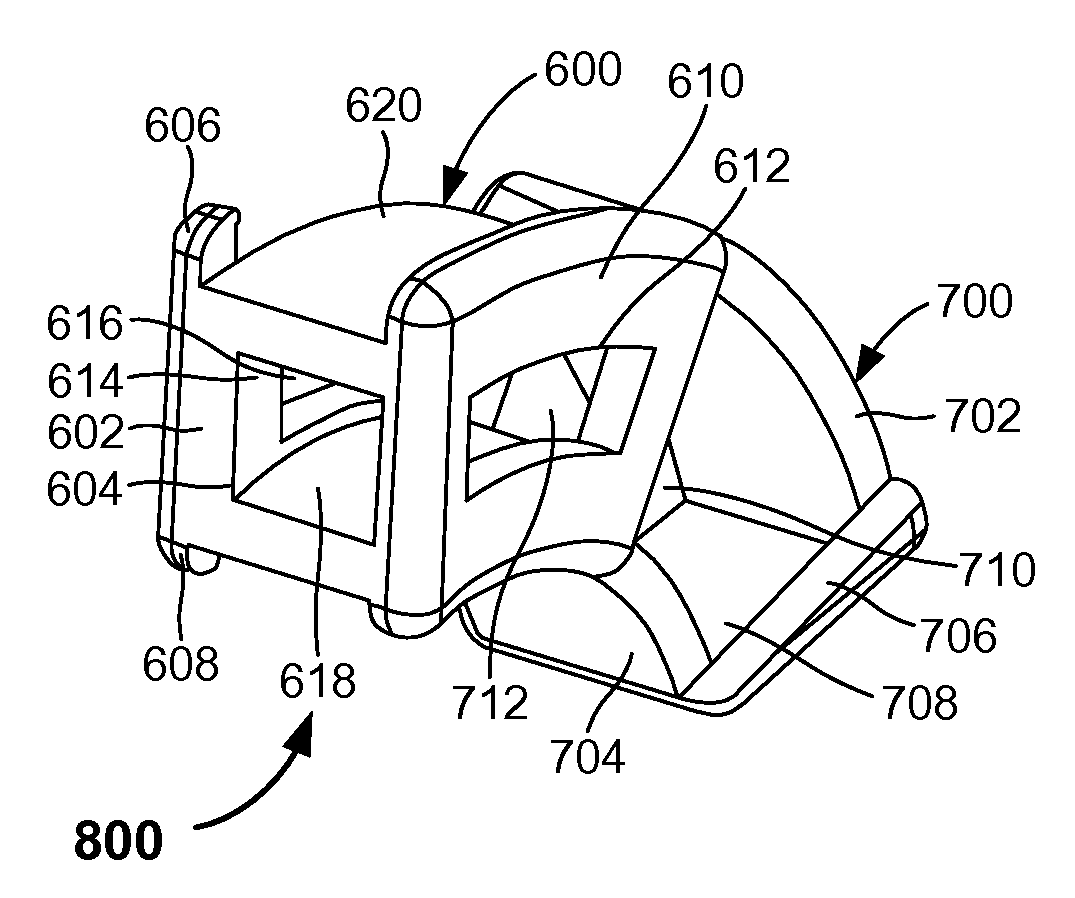
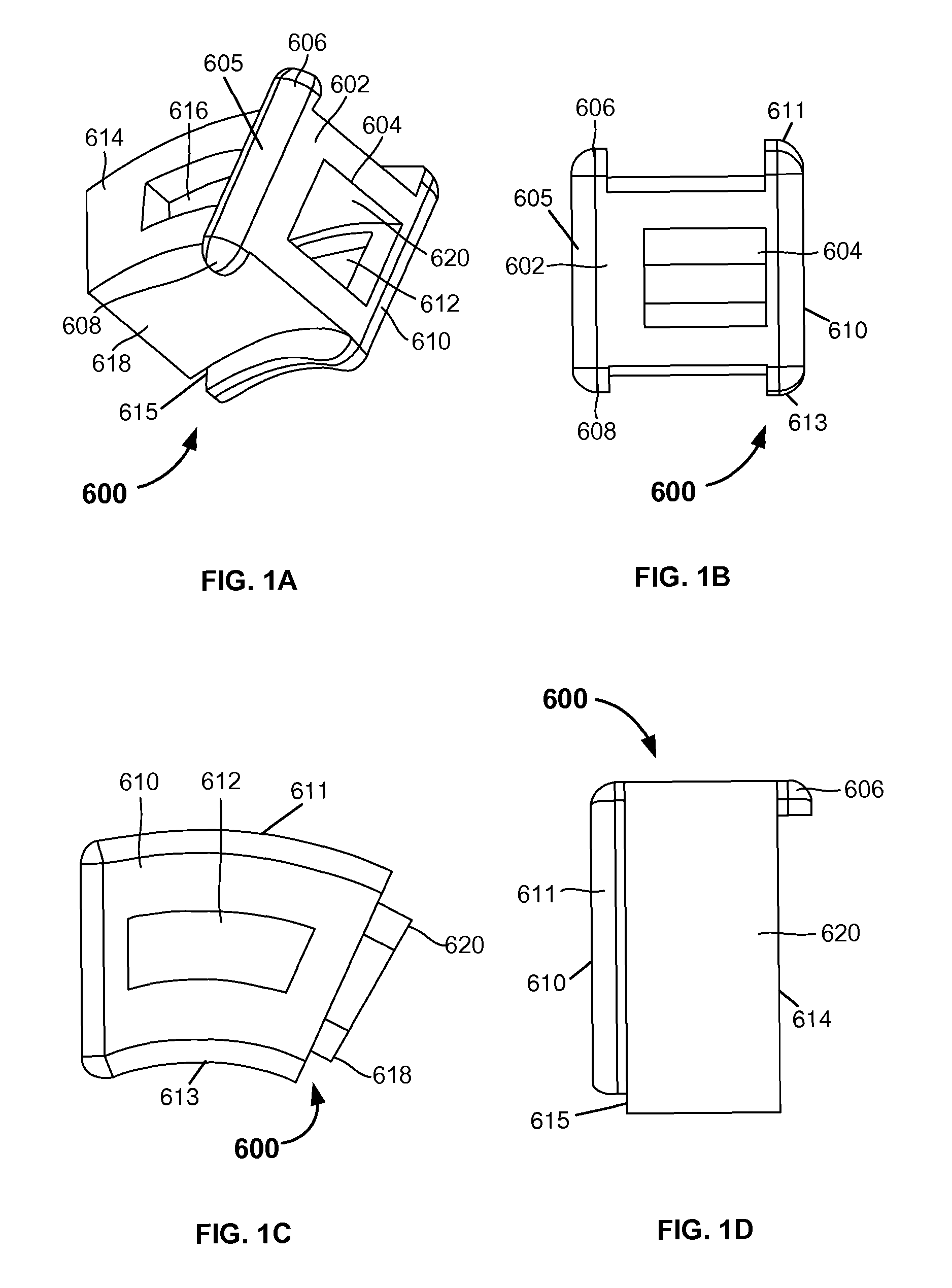
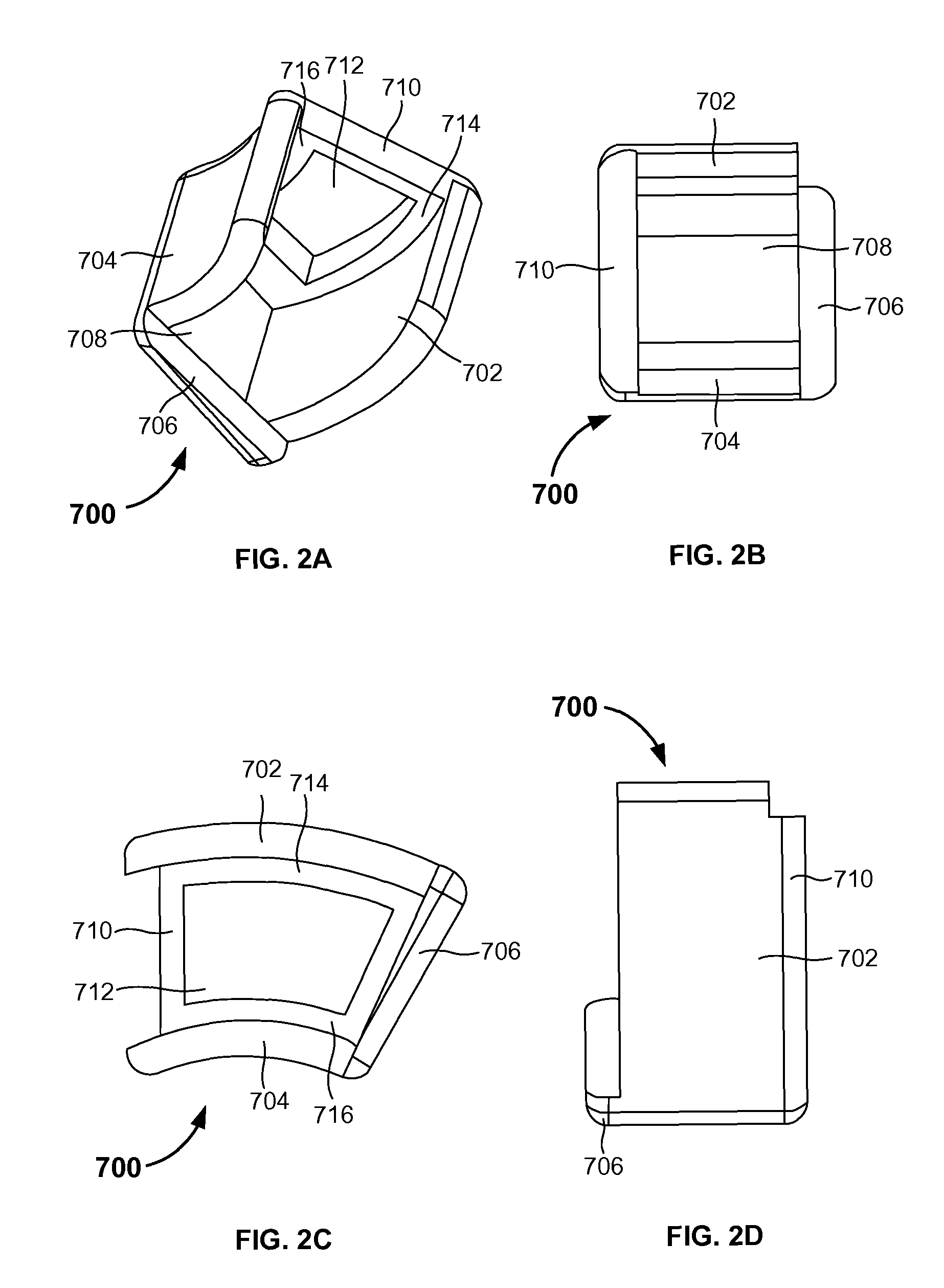
[0022]As previously mentioned, there remains a need for a new intervertebral implant to restore motion in a patient's back in a controlled manner while permitting natural motion with stability. The embodiments herein achieve this by providing a sliding intervertebral implant that attaches to a ...


PUM


Abstract

A sliding intervertebral implant and method includes a first member that connects to an intervertebral space between two adjacent vertebrae. The first member includes a pair of curved side walls connected to each of a front wall, an upper curved wall, and a lower curved wall, wherein a length of a first curved side wall is less than a length of each of a second curved side wall, the upper curved wall, and the lower curved wall, and wherein an edge of the second curved side wall is offset from an edge of the front wall. A second member is slidably attached to the first member, and includes a top and bottom curved wall each connected to an inclined side wall and a guide wall, wherein the guide wall comprises grooves, wherein the second curved side wall of the first member slides in the grooves of the guide wall.

Description

BACKGROUND[0001]1. Technical Field[0002]The embodiments herein generally relate to medical devices, and, more particularly, to a sliding intervertebral implant used during orthopedic surgeries.[0003]2. Description of the Related Art[0004]Spinal fusion procedures may comprise the entire removal of the degenerated intervertebral disc between two adjacent vertebrae and the insertion of an implant within the intervertebral space. The implant may be positioned to maintain the spine alignment and the height and angle of the intervertebral space by pushing the vertebrae apart from each other, which helps in providing stability and proper maneuvering of the spine. Lastly, fusion material may be placed within the intervertebral space, which along with the body's natural cells, promotes bone formation. The fusion occurs between the endplates of the vertebrae.[0005]A variety of implants of different configurations for intervertebral space have been developed to accomplish the spinal fusion sur...

Claims


Application Information

Patent Timeline
Patent Type & Authority Patents(United States)
IPC IPC(8): A61B17/70A61F2/44
CPCA61F2/4455A61F2002/2835A61F2002/30383A61F2002/30476A61F2002/3055A61F2002/30579A61F2220/0025A61F2250/0007
Inventor OH, YOUNGHOONABDELGANY, MAHMOUD F.
Owner CUSTOM SPINE INC
Why Eureka
Try Eureka