Minimally invasive spinal disc stabilizer and insertion tool

Inactive Publication Date: 2007-12-27
GLENN BRADLEY J +1
View PDF50 Cites 227 Cited by
  • Summary
  • Abstract
  • Description
  • Claims
  • Application Information

AI Technical Summary

Benefits of technology

[0013] There are two general approaches to an artificial disc: one is a complete replacement of the entire joint, where an articulated prosthesis is solidly attached to the adjacent vertebra. A second approach is to replace only the center “nucleus” of the disc with an implant which provides compliant support in the center of the disc space but retains the native support of the annulus fibrosis and supportive ligame

Problems solved by technology

The spinal disc may be displaced or damaged due to trauma, disease, degenerative defects, or wear over an extended period of time.
The mass of a herniated or “slipped” nucleus tissue can compress a spinal nerve, resulting in leg pain, loss of muscle control, or even paralysis.
As these overlapping laminated plies of the annulus begin to buckle and separate, either circumferential or radial annular tears may occur, which may contribute to persistent or disabling back pain.
Adjacent, ancillary spinal facet joints will also be forced into an overriding position, which may create additional back pain.
Back pain related to the aforementioned damaged or displaced intervertebral disc is a very common health problem, affecting the majority of people at some point in their life.
While this treatment alleviates the pain, all discal motion is lost in the fused segment.
Ultimately, this procedure places a greater stress on the discs adjacent to the fused segment as they compensate for lack of motion, perhaps leading to premature degeneration of those adjacent discs.
Beyond the questionable applicability of the devices is the inherent difficulties encountered during implantation.
Due to their size and inflexibility

Method used


Image

  • Minimally invasive spinal disc stabilizer and insertion tool
  • Minimally invasive spinal disc stabilizer and insertion tool
  • Minimally invasive spinal disc stabilizer and insertion tool

Examples


Embodiment Construction

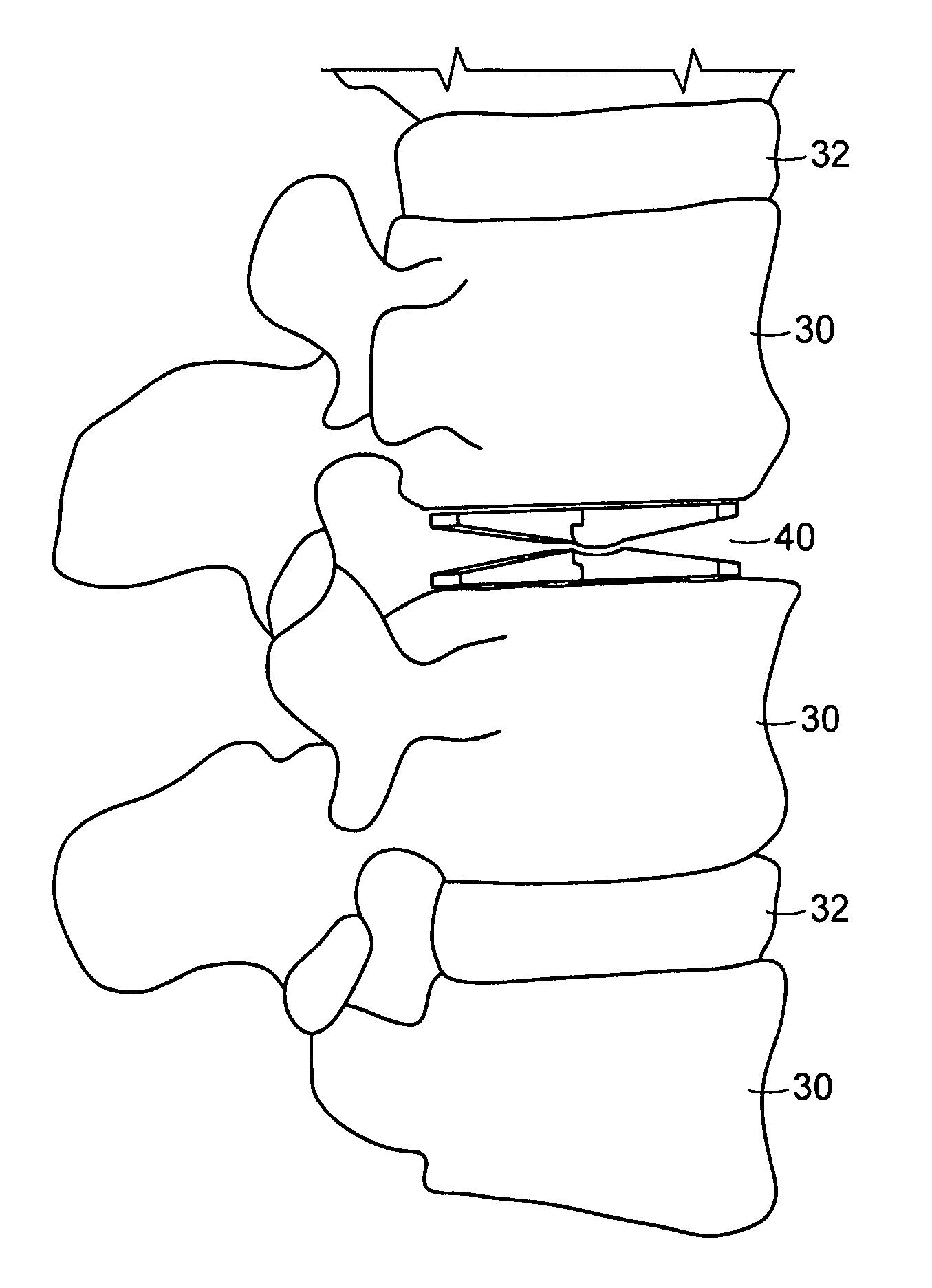
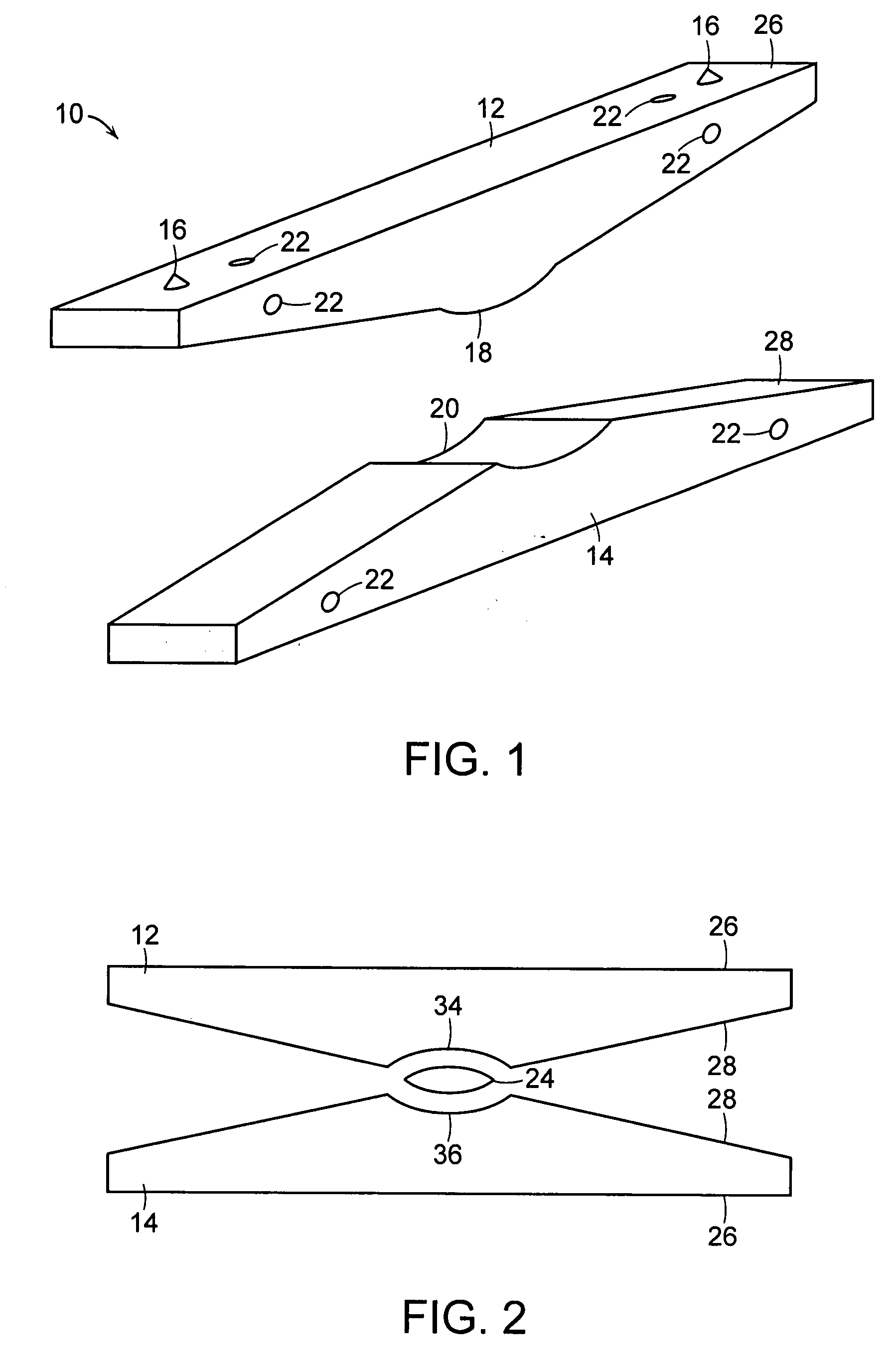
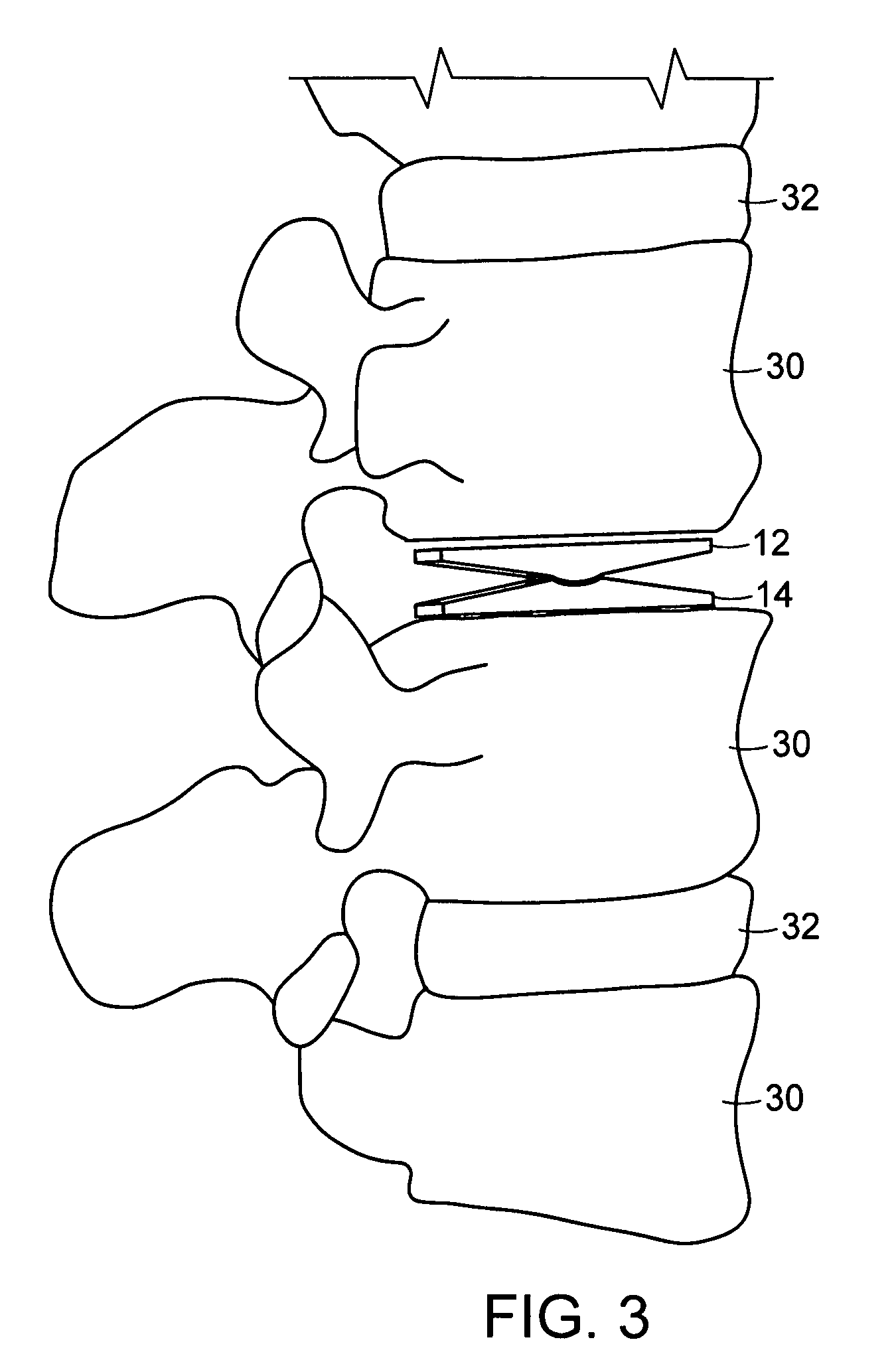
[0095] The invention provides an apparatus for implantation between two vertebrae of a spinal column to replace or alleviate stress upon an intervertebral disc. The apparatus comprises at least one upper assembly and one lower assembly that can articulate about a mechanical connection between the upper and lower assemblies, thus allowing for controlled relative motion of the at least two assemblies. As a result, when placed between and attached to or resting against two vertebrae, the implant permits controlled motion between vertebral segments of the axial skeleton, similar to that provided by the intervertebral disc being replaced or supported.

[0096] The invention also provides a method and apparatus for implanting the apparatus within the intervertebral space. The method employs a minimally invasive or open lateral, anterior-lateral, or posterior-lateral approach that minimizes soft tissue damage around the implant. The apparatus for inserting the implant may be used both to ins...


PUM

PropertyMeasurementUnit
Angleaaaaaaaaaa
Angleaaaaaaaaaa
Lengthaaaaaaaaaa

Abstract

The invention relates to a spinal implant to be inserted between two vertebra to support and stabilize adjacent vertebra and allow for physiological motion. One embodiment of the implant includes an upper assembly and a lower assembly, where the assemblies are adapted to articulate relative to one another. This implant also includes elongate elements that are deployable between a closed position and an open position. Portions of the implant can interlock to form various shapes. The invention includes an implantable device to support the vertebrae, and a minimally invasive method for inserting and deploying the device within the intervertebral space.

Description

CROSS-REFERENCE TO RELATED APPLICATIONS [0001] This application claims priority to and the benefit of U.S. provisional patent application Ser. No. 60 / 629,892, filed Nov. 23, 2004, and U.S. provisional patent application Ser. No. 60 / 665,874, filed Mar. 29, 2005, the disclosures of which are being incorporated herein by reference in their entirety.FIELD OF THE INVENTION [0002] The present invention relates generally to the field of spinal implants and, more particularly, to an implant that is configured to be placed within an intervertebral space in order to support and stabilize adjacent vertebra and allow for physiological motion. BACKGROUND OF THE INVENTION [0003] The vertebrate spine is the axis of the skeleton on which a substantial portion of the weight of the body is supported. In humans, the normal spine has seven cervical, twelve thoracic and five lumbar segments. The lumbar spine sits upon the sacrum, which then attaches to the pelvis, and in turn is supported by the hip and...

Claims


Application Information

Patent Timeline
IPC IPC(8): A61F2/44
CPCA61F2/4425A61F2310/00976A61F2002/30093A61F2002/30116A61F2002/30135A61F2002/30153A61F2002/30166A61F2002/30172A61F2002/30177A61F2002/30179A61F2002/30181A61F2002/30301A61F2002/30329A61F2002/30369A61F2002/30433A61F2002/30538A61F2002/30556A61F2002/30571A61F2002/30579A61F2002/30599A61F2002/30604A61F2002/30624A61F2002/30649A61F2002/30774A61F2002/30836A61F2002/30841A61F2002/443A61F2002/4627A61F2002/4629A61F2210/0019A61F2220/0025A61F2220/0033A61F2220/0041A61F2230/0004A61F2230/0006A61F2230/0019A61F2230/0028A61F2230/0052A61F2230/0056A61F2230/0058A61F2230/006A61F2230/0095A61F2250/0006A61F2250/0009A61F2250/0063A61F2310/00017A61F2310/00023A61F2310/00029A61F2310/00047A61F2310/00059A61F2310/00131A61F2310/00155A61F2310/0097A61F2/4611A61F2002/30092A61F2002/30136
Inventor GLENN, BRADLEY J.SCHNEIDERMAN, GARY A.
Owner GLENN BRADLEY J
Why Eureka
Try Eureka