Fusion implant device and method of use

a fusion implant and implant technology, applied in the field of osteogenic interbody fusion implant devices, can solve the problems of implant fitting certain ideal criteria for interbody fusion grafts, implant compression near the affected area, and irritated nerves,

Inactive Publication Date: 2001-11-13
WARSAW ORTHOPEDIC INC
View PDF40 Cites 230 Cited by
  • Summary
  • Abstract
  • Description
  • Claims
  • Application Information

AI Technical Summary

Problems solved by technology

When one or more disks degenerate through accident or disease, nerves passing near the affected area may be compressed and are consequently irritated.
The result may be chronic and/or debilitating back pain.
Furthermore, the material from which the fusion graft is made should be biocompatible and closely mimic the body's naturally occurring tissues.
Unfortunately, those implants may not fit certain ideal criteria for an interbody fusion graft.
For example, many of the implants such as the one desc...

Method used


Image

  • Fusion implant device and method of use
  • Fusion implant device and method of use
  • Fusion implant device and method of use

Examples


Embodiment Construction

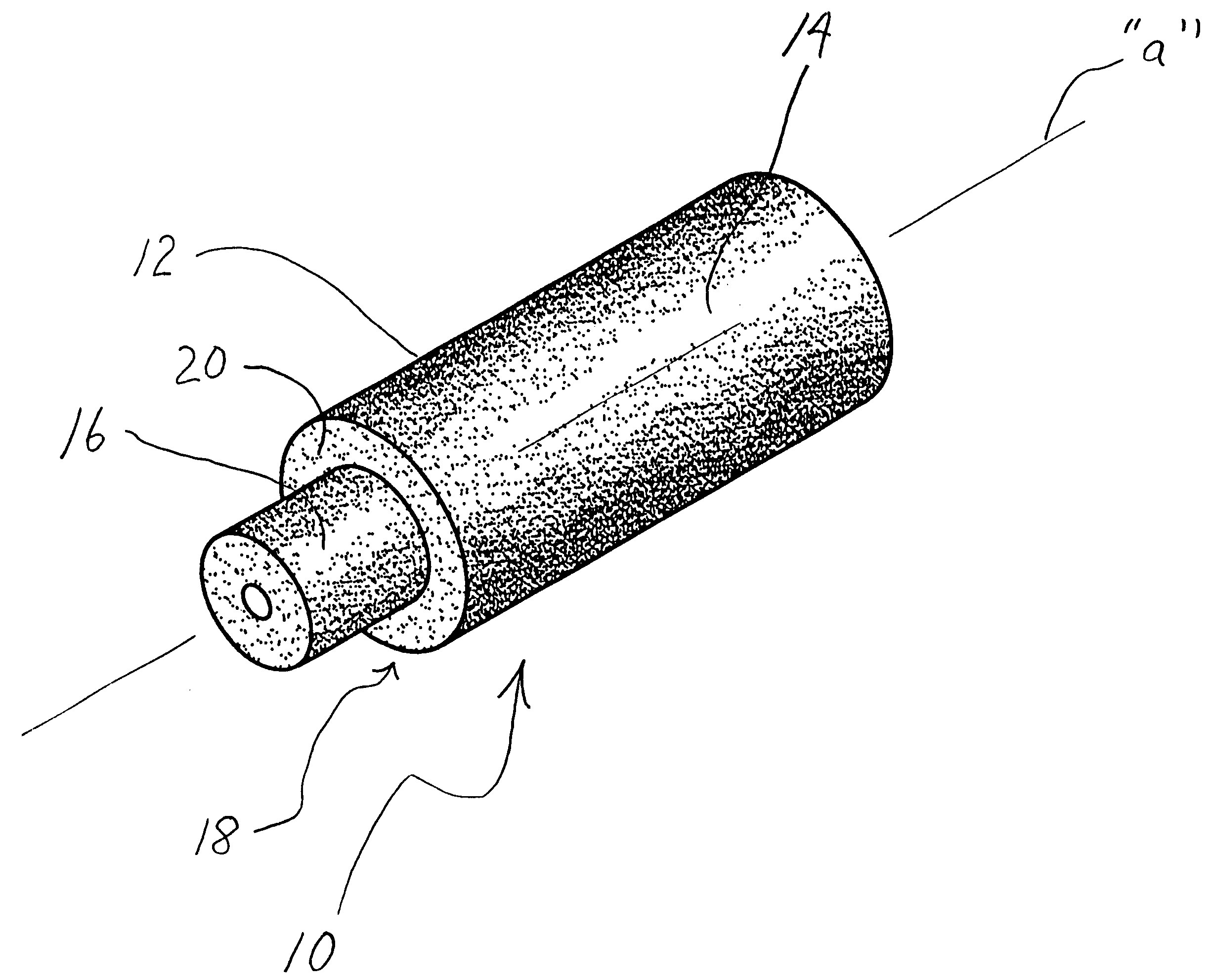
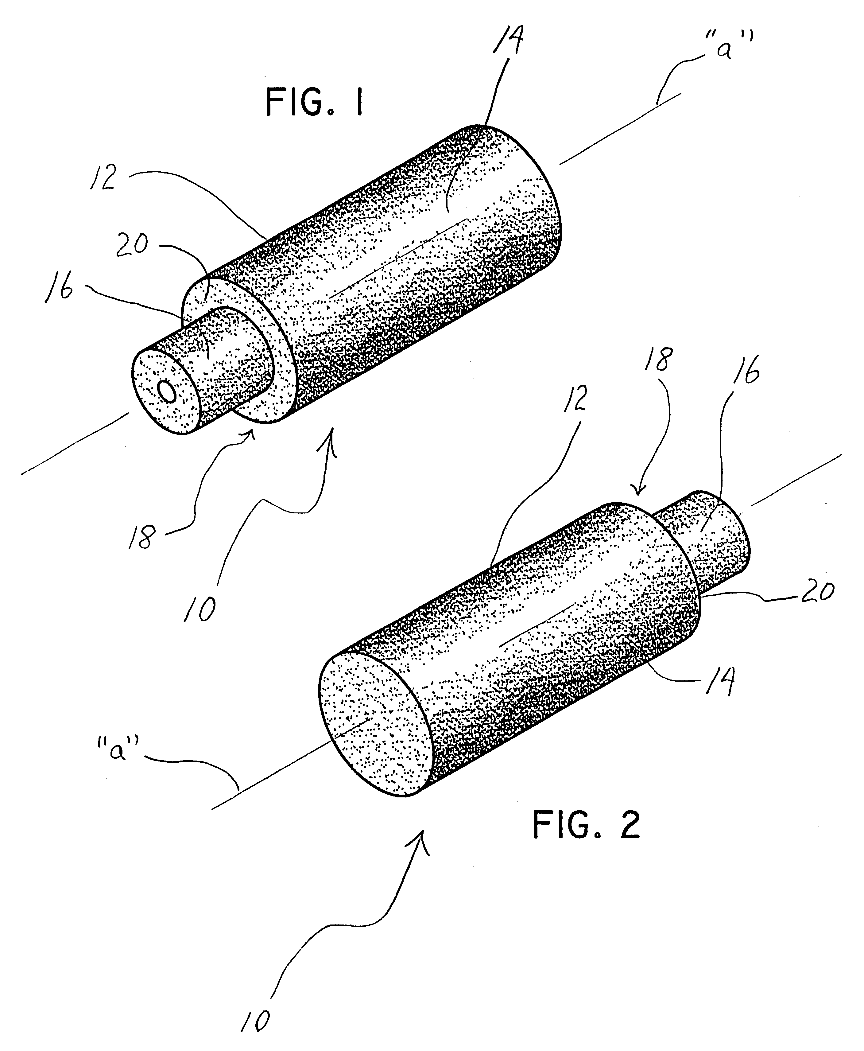
FIGS. 20-25 illustrate alternate embodiments of the stepped fusion implant of the present invention. Fusion implant 40 of FIG. 20 is a multi-step configuration defined by a plurality of alternating sections 42, 44 of different cross-sectional dimensions. In particular, implant section 42 has a first diameter which is less than the diameter of second implant section 44. The junctures of the first and second implant sections 42,44 define stepped regions with retaining surfaces 46 which engage corresponding structure defined by the receiving bed within the adjacent vertebrae. FIG. 21 illustrates another multi-step implant 50 where the implant sections 52,54, 56,58 sequentially increase in cross-sectional dimension from one end of the implant to the other end to define a multitude of retaining surfaces 53,55,57. FIG. 22 depicts a single step fusion implant 60 similar to the implant of FIGS. 1-3. However, in accordance with this embodiment, it is contemplated that the smaller implant sec...


PUM


Abstract

An intervertebral prosthesis includes a bone graft implant member dimensioned for insertion within an intervertebral space defined between adjacent vertebrae and having at least first and second longitudinal sections with respective first and second cross-sectional dimensions. The first cross-sectional dimension of the first implant section is greater than the second cross-section dimension of the second implant section to define a stepped region having a retaining surface. Consequently, upon insertion of the implant member within a generally correspondingly dimensioned receiving bed formed within the adjacent vertebrae, the retaining surface facilitates securement therewithin by corresponding engagement with surfaces of the receiving bed. A method for fusion of adjacent vertebrae utilizing the prosthesis is also disclosed.

Description

1. Field of the InventionThe present invention relates to an osteogenic interbody fusion implant device and, more particularly, to a non-threaded intervertebral bone implant having a stepped configuration which facilitates securement of the implant within the intervertebral site.2. Description of the Related ArtThe spine is a flexible column formed of a series of bone called vertebrae. The vertebrae are hollow and piled one upon the other, forming a strong hollow column for support of the cranium and trunk. The hollow core of the spine houses and protects the nerves of the spinal cord. The different vertebrae are connected together by means of articular processes and intervertebral, fibro-cartilagineous spaces.The intervertebral fibro-cartilages are also known as intervertebral disks and are made of a fibrous ring filled with pulpy material. The disks function as spinal shock absorbers and also cooperate with synovial joints to facilitate movement and maintain flexibility of the spi...

Claims


Application Information

Patent Timeline
IPC IPC(8): A61B17/16A61F2/28A61F2/44A61F2/46A61F2/30A61F2/00A61B17/02
CPCA61B17/1637A61B17/1671A61F2/28A61F2/4455A61F2/446A61F2/4644A61B2017/0256A61F2002/2817A61F2002/2835A61F2002/30233A61F2002/30266A61F2002/30785A61F2002/30787A61F2002/30828A61F2002/4475A61F2002/448A61F2230/0069A61F2230/0082A61F2310/00017A61F2310/00023A61F2310/00179Y10S606/907Y10S606/91Y10S606/909Y10S606/913A61F2002/30593
Inventor SCARBOROUGH, NELSONMORRIS, JOHN W.
Owner WARSAW ORTHOPEDIC INC
Why Eureka
Try Eureka