Percutaneous spine distraction implant systems and methods

a technology of implant systems and spines, applied in the field of spinal cord and nerve root pressure relief, can solve the problems of inability to fully fully fully discharge, inability to fully discharge, etc., to achieve the effect of relieving the pressure on the spinal cord and/or nerve roots

Inactive Publication Date: 2005-07-28
REILEY MARK A
View PDF0 Cites 540 Cited by
  • Summary
  • Abstract
  • Description
  • Claims
  • Application Information

AI Technical Summary

Problems solved by technology

However, symptoms such as pain, weakness, and / or numbness appear when the narrowing leads to compression of the spinal cord and nerve roots.
Cervical spinal stenosis may cause similar symptoms in the shoulders, arms, and legs; hand clumsiness and gait and balance disturbances can also occur.
In severe cases, the pain can be constant, excruciating, and debilitating.
Typically, however, spinal stenosis occurs as the gradual result of aging and “wear and tear” on the spine during everyday activities.
These surgical techniques, though effective for many, are invasive.
Due to the obvious risks involved, many surgeons will not consider open surgical treatment of spinal stenosis unless several months of non-surgical treatment methods have been tried.

Method used


Image

  • Percutaneous spine distraction implant systems and methods
  • Percutaneous spine distraction implant systems and methods
  • Percutaneous spine distraction implant systems and methods

Examples


Embodiment Construction

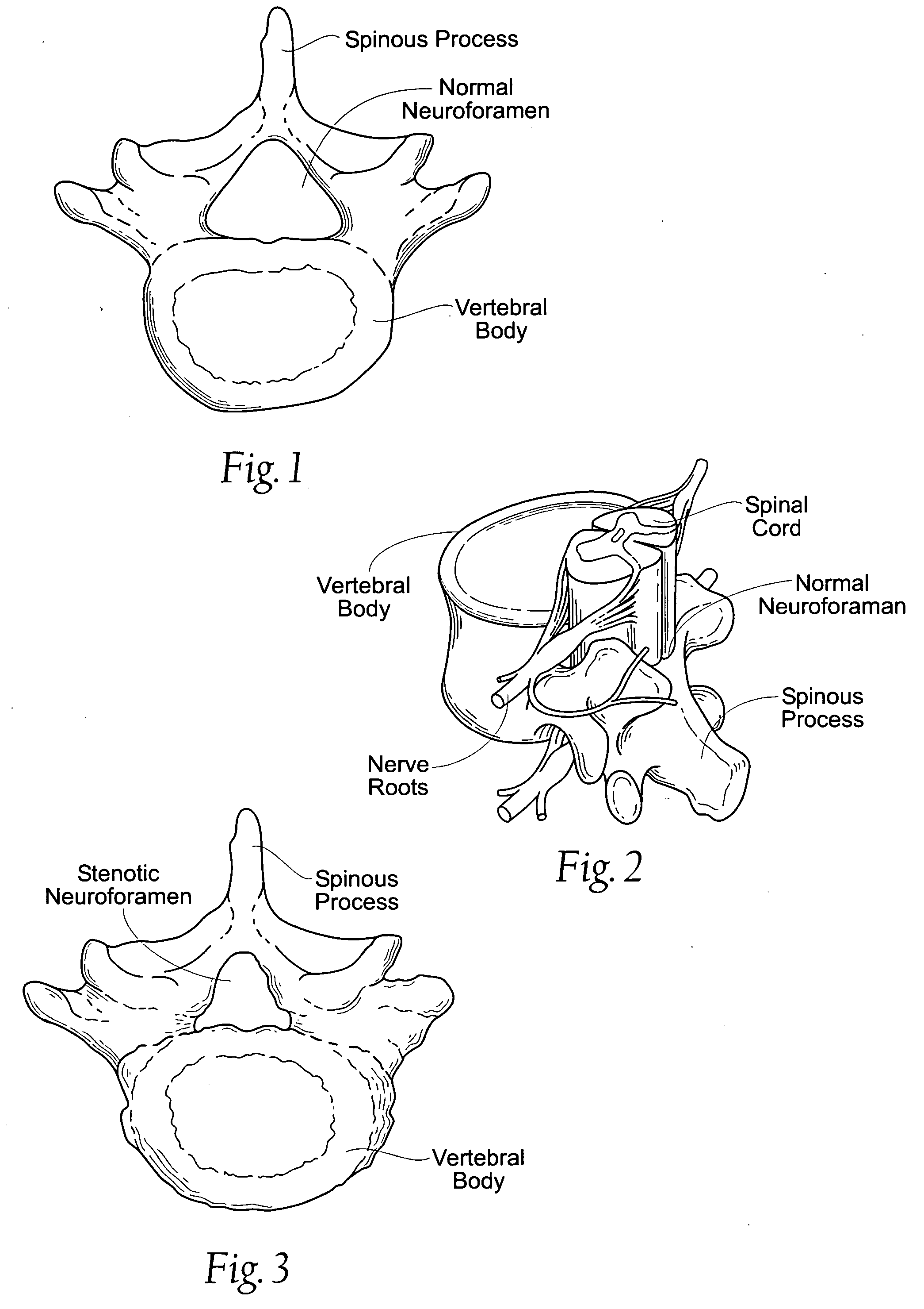
[0038]FIG. 1 shows a vertebra with a normal neuroforamen. FIG. 2 shows the passage of the spinal cord and nerve roots in a normal neuroforamen.

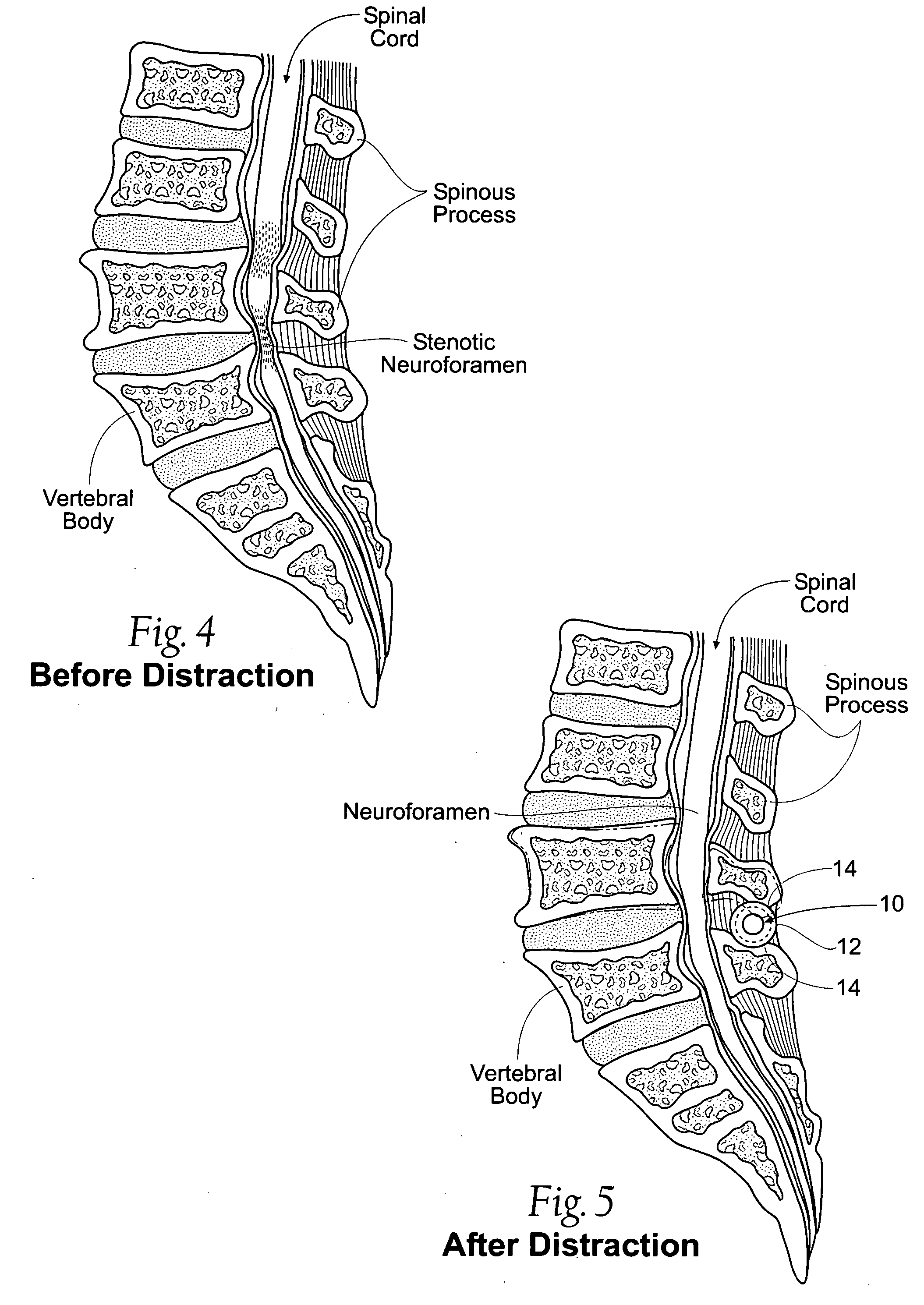
[0039]FIG. 3 shows a vertebra with a stenotic neuoforamen, i.e., a neuroforamen that has a reduced sized, compared to the neuroforaman shown in FIG. 1. As FIG. 4 shows, the narrowing of the spaces in the spine that results in pressure on the spinal cord and / or nerve roots. When the neuroforamina are reduced in size, the nerves may swell and become inflamed, causing pain and discomfort.

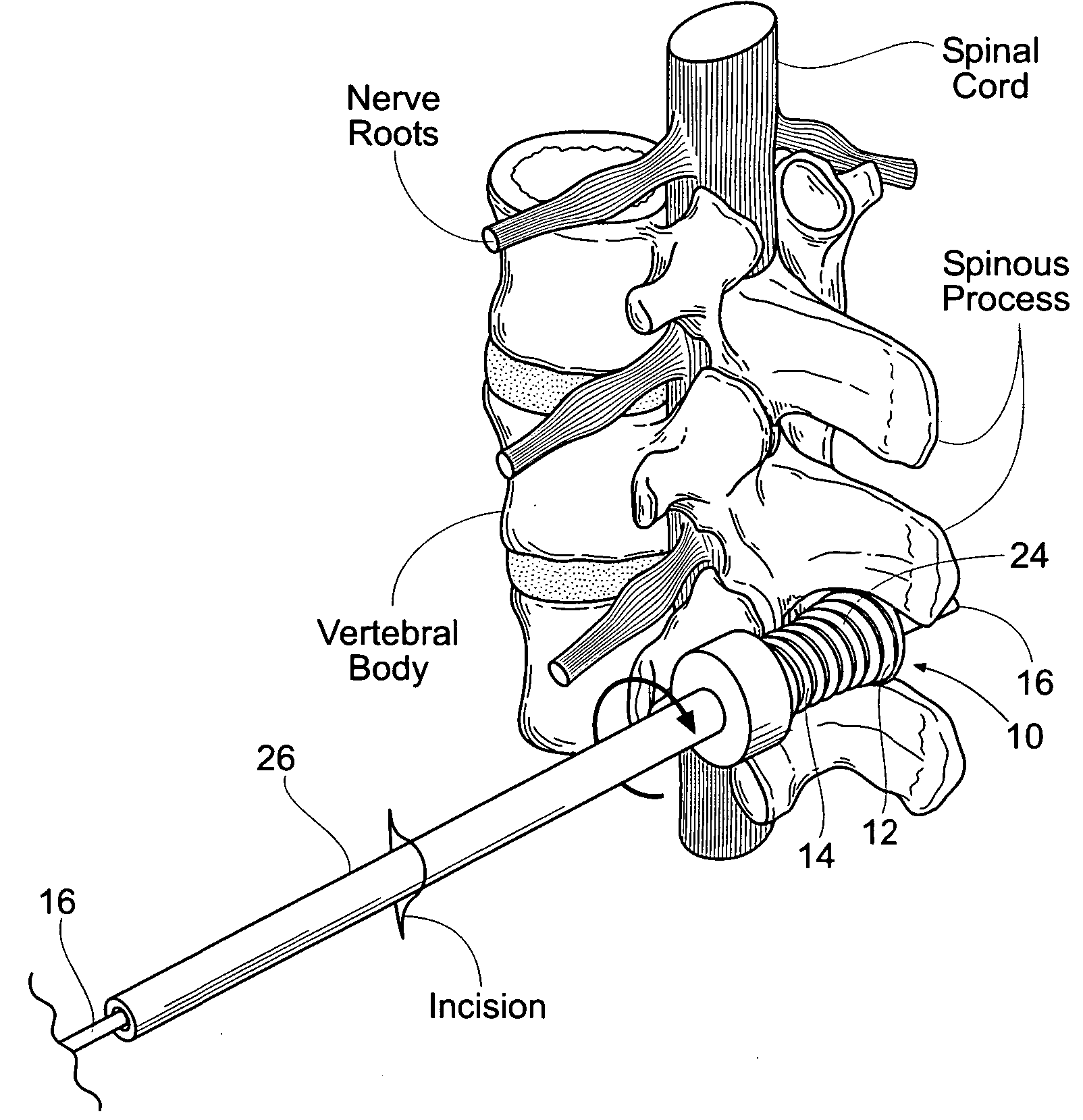
[0040]FIG. 5 shows a device 10 that has been implanted by percutaneous access between adjacent first and second spinous processes of the stenotic vertebrea shown in FIG. 4. The device 10 relieves the pressure on the spinal cord and / or nerve roots. FIG. 6 shows the device 10 as it exists outside the body, prior to implantation. The device 10 can be made of a durable prosthetic material, such as, e.g., polyethylene, rubber, a sponge material (e.g., polyethylene ...


PUM


Abstract

Systems and methods for treating spinal stenosis insert a guide element percutaneously into proximity with the adjacent spinous processes. The systems and methods direct an implant device over the guide element to a position resting between the adjacent spinous processes. The device is sized and configured to distend the adjacent spinous processes. The implant device itself can be variously constructed. It can, e.g., possess threaded lands and / or a notched region in which a spinous process can rest. The implant device has a lumen to accommodate passage of the guide element, so that the device can be passed percutaneously over the guide element for implantation between adjacent spinous processes.

Description

RELATED APPLICATIONS [0001] This application claims the benefit of provisional U.S. Application Ser. No. 60 / 539,208, filed Jan. 26, 2004, and provisional U.S. Application Ser. No. 60 / 600,039, filed Aug. 9, 2004.FIELD OF THE INVENTION [0002] The invention generally relates to systems and methods for treating conditions of the spine, and, in particular, systems and methods for distending the spine and / or blocking and / or limiting spinal extension for treating, e.g., spinal stenosis. BACKGROUND OF THE INVENTION [0003] Spinal stenosis is a narrowing of the spinal canal. The narrowing of the spinal canal itself does not usually cause any symptoms. However, symptoms such as pain, weakness, and / or numbness appear when the narrowing leads to compression of the spinal cord and nerve roots. The nerves react by swelling and undergoing inflammation. [0004] While spinal stenosis can be found in any part of the spine, the lumbar and cervical areas are the most commonly affected. Patients with lumb...

Claims


Application Information

Patent Timeline
Patent Type & Authority Applications(United States)
IPC IPC(8): A61B17/02A61B17/70A61B17/88A61F2/44
CPCA61B17/025A61B17/7062A61B2017/0256A61B2017/00557A61B17/7065
Inventor REILEY, MARK A.
Owner REILEY MARK A
Why Eureka
Try Eureka