Prosthetic spinal disc replacement

a spinal disc and prosthesis technology, applied in the field of prosthetic spinal discs, can solve the problems of spinal disc displacement or damage, leg pain, loss of muscle control, persistent or disabling back pain,

a spinal disc and prosthesis technology, applied in the field of prosthetic spinal discs, can solve the problems of spinal disc displacement or damage, leg pain, loss of muscle control, persistent or disabling back pain,

US20050043800A1Active Publication Date: 2005-02-24GLOBUS MEDICAL INC

Image

  • Prosthetic spinal disc replacement
  • Prosthetic spinal disc replacement
  • Prosthetic spinal disc replacement

Examples


Embodiment Construction

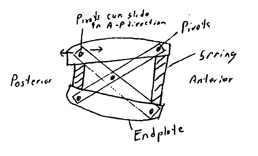
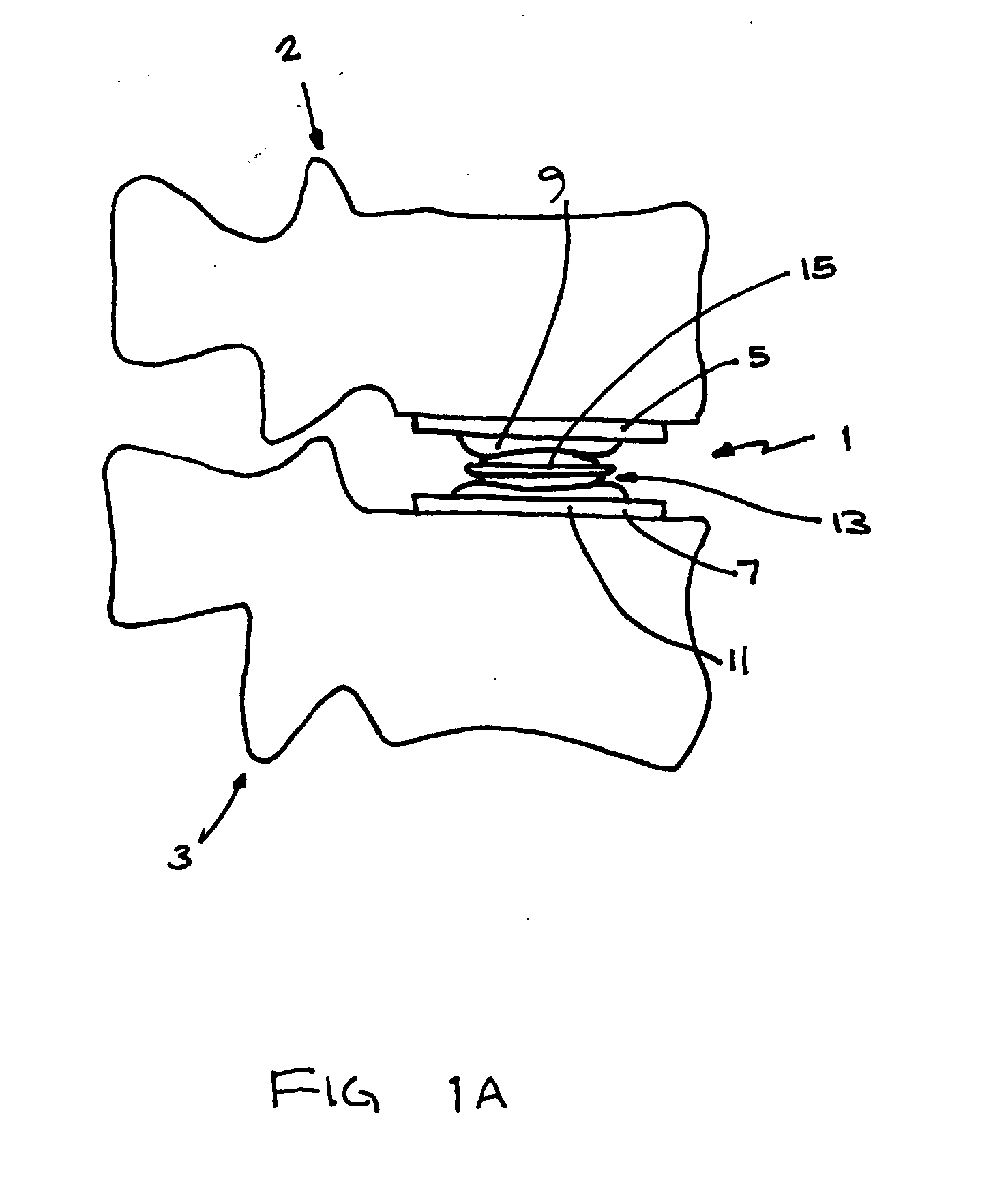
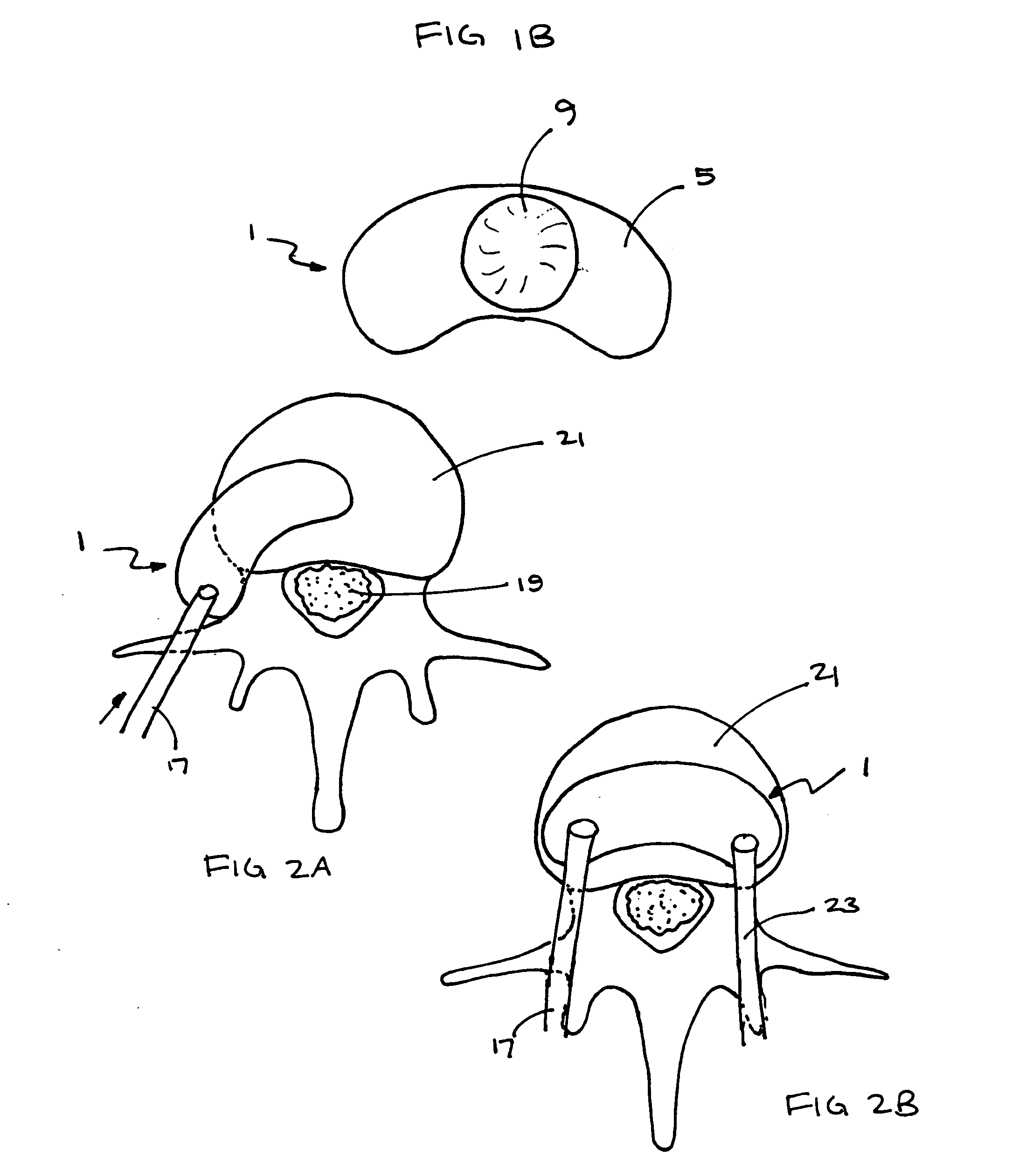
[0047] The present invention relates generally to a posterior prosthetic spinal disc for replacing a damaged disc between two vertebrae of a spine. The present invention also relates to a method for implanting a prosthetic spinal disc via posterior or posterior lateral implantation. In particular, the present invention encompasses a method for implanting the prosthetic spinal disc while avoiding or minimizing contact with the spinal cord.

[0048] As described in greater detail below, the prosthetic spinal disc may be articulating or non-articulating. In addition, the prosthetic disc may be formed of one, two, three or more units. For example, two units may be disposed in the medial-lateral direction at spaced apart locations, and the upper and lower portions of each unit have interfacing surfaces that form an arc in the anterior-posterior direction.

[0049] If multiple units are used, they may be spaced apart from each other or connected to prior to insertion in the patient or as they...


PUM

PropertyMeasurementUnit
angleaaaaaaaaaa
angleaaaaaaaaaa
total axial rotationaaaaaaaaaa

Abstract

The present invention relates generally to a prosthetic spinal disc for replacing a damaged disc between two vertebrae of a spine. The present invention also relates to a method for implanting a prosthetic spinal disc via posterior or posterior lateral implantation. Other surgical approaches for implanting the prosthetic disc may also be used. The present invention also involves a method for implanting the prosthetic spinal disc while either avoiding or minimizing contact with the spinal cord and nerve rootlets, or reducing the time and extent that they need to be repositioned during implantation.

Description

CROSS REFERENCE TO RELATED APPLICATIONS [0001] This application claims priority to provisional application serial No. 60 / 491,271 filed on Jul. 31, 2003 and entitled “Posterior Prosthtetic Spinal Disc”, the entirety of which is incorporated herein by reference thereto.FIELD OF THE INVENTION [0002] The present invention relates to a prosthetic spinal disc for fully or partially replacing a damaged disc between two vertebrae of a spine. The present invention also relates to a method for implanting a prosthetic spinal disc via posterior or posterior lateral implantation, although other implantation approaches may also be used. BACKGROUND OF THE INVENTION [0003] The vertebrate spine is the axis of the skeleton on which a substantial portion of the weight of the body is supported. In humans, the normal spine has seven cervical, twelve thoracic and five lumbar segments. The lumbar spine sits upon the sacrum, which then attaches to the pelvis, and in turn is supported by the hip and leg bon...

Claims


Application Information

Patent Timeline
24 Feb 2005
Publication
US20050043800A1
IPC
A61B17/00; A61B17/02; A61B17/16; A61B17/17; A61B17/90; A61F; A61F2/00; A61F2/02; A61F2/30; A61F2/44
CPC
A61B17/1604; A61F2310/00796; A61B17/1735; A61B17/1757; A61B2017/0046; A61B2017/0256; A61F2/442; A61F2/4425
Inventors
PAUL, DAVID C.; ANGELUCCI, CHRISTOPHER