Artificial spinal unit assemblies

Active Publication Date: 2005-02-10
FLEXUSPINE
View PDF99 Cites 463 Cited by
  • Summary
  • Abstract
  • Description
  • Claims
  • Application Information

AI Technical Summary

Benefits of technology

[0023] In addition, another embodiment of the artificial facet joint is disclosed that generally comprises two locked pedicle screws joined by a rod having a ball and socket joint centrally located on the rod between the two pedicle screws. The locking of the pedicle screws prevents the screw head from swiveling, but allows rotation and translation of the rod.
[0024] While conventional locking type pedicle screws may be employed, a novel locking type pedicle screw is also disclosed. Locking type pedicle screws comprise a set screw located in the pedicle screw head, which applies force to the retaining rod as it is tightened. One the set screw is tightened, rotational and translational movement of the rod within the head of the pedicle screw is prohibited. In addition, the multi-axial movement of the pedicle screw head is also prohibited making the entire assembly a fixed structure. By employing the rod holding device described in detail below, the set screw can be tightened and the multi-axial movement of the pedicle screw head can be prohibited without limiting the translational and rotational movement of the retaining rod. The rod holding device generally comprises a solid insert fitting within the pedicle screw head with a hole in which the retaining rod is slidingly positioned. As the set screw is tightened, force is applied to the rod holding device and transferred to the bottom of the pedicle screw head without applying force to the retaining rod. This allows fixation of the pedicle screw head without limiting movement of the retaining rod.
[0025] In another preferred embodiment, the artificial facet joint generally comprises an upper and lower pedicle screw having post-type heads. Rather than the previously described rod, a retaining plate is employed. Elongated holes are defined through the retaining plate, which are positioned upon the post-type heads of the pedicle screws. The post-type heads are allowed to move within the elongated holes, providing limited range of motion. Employing cushioning pads made of rubber or similar biocompatible material may dampen the movement of the plate. The post-type heads may also comprise threaded or lockable caps to prevent dislocation of the plate from the post-type heads.
[0026] In instances where a fusion procedure is unavoidable, a PLIF and TLIF cages are disclosed that utilize the expansion principal of the functional artificial intervertebral implant. One embodiment of the PLIF and TLIF cages generally comprises three parts: An external body, an internal body, and an expansion device. The external and internal bodies will have substantially the same shape and will be shaped accordingly to the procedures for which they will be used, more specifically, a rectangular cage is preferred for a PLIF procedure and round or banana shaped cage is preferred for the TLIF procedure. Both the external and internal bodies comprise a mesh structure in which an osteoconductive substance can be placed (i.e. morsilized autograph or an osteobiologic substitute). The external body of the cage contains an internal void space that houses the internal body. The external body further comprises an expansion window on its superior surface through wh

Problems solved by technology

Placement of posterior devices that maintain mobility in the spine have been limited due to the relatively small opening that can be afforded posteriorly between the exiting and transversing nerve roots.
Additionally, placement of posterior interbody devices requires the removal of one or both facet joints, further destabilizing the spine.
Thus conventional posteriorly placed

Method used


Image

  • Artificial spinal unit assemblies
  • Artificial spinal unit assemblies
  • Artificial spinal unit assemblies

Examples


Embodiment Construction

[0073] In the following detailed description of the preferred embodiments, reference is made to the accompanying drawings, which form a part hereof, and in which are shown by way of illustration specific embodiments in which the invention may be practiced. It is to be understood that other embodiments may be utilized and structural changes may be made without departing from the scope of the present invention.

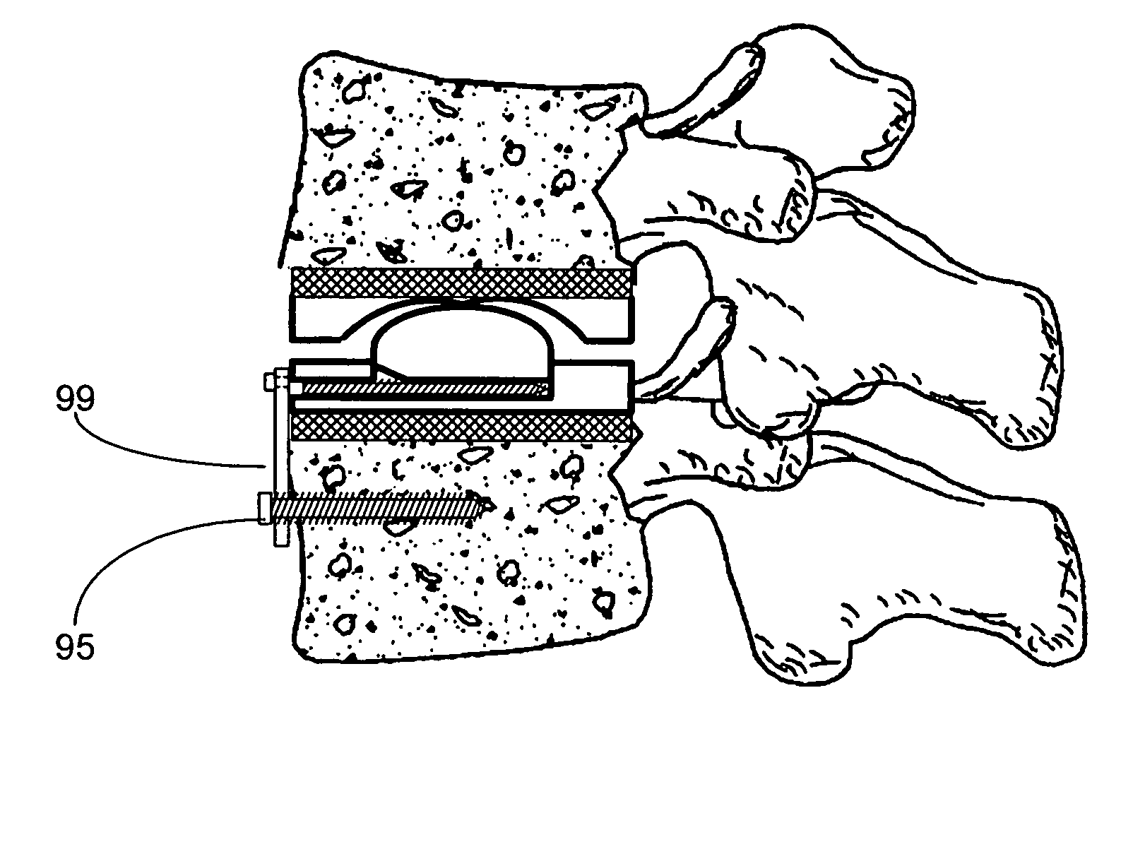
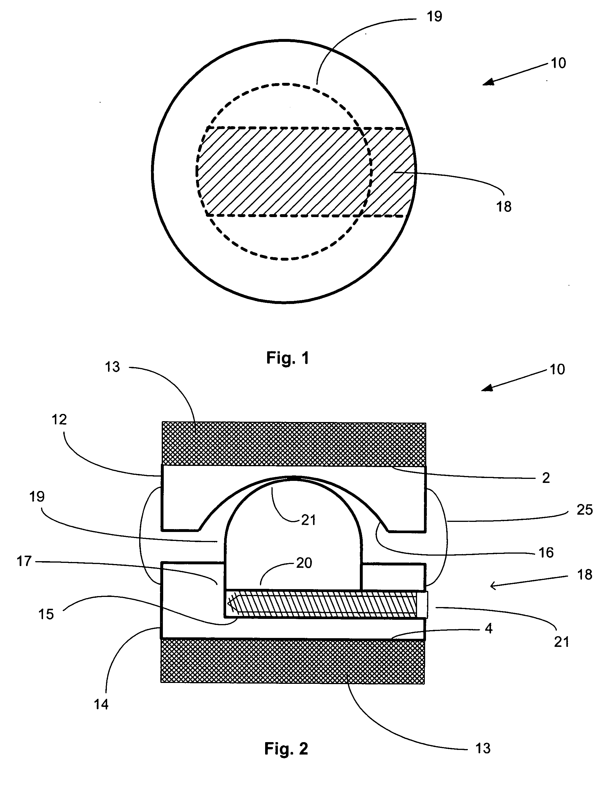
[0074]FIGS. 1 and 2 show a round, expandable artificial intervertebral implant designated generally at 10. The device is implemented through a posterior surgical approach by making an incision in the anulus connecting adjacent vertebral bodies after removing one or more facet joints. The natural spinal disc is removed from the incision after which the expandable artificial intervertebral implant is placed through the incision into position between the vertebral bodies. The implant is preferably made of a biocompatible metal having a non-porous quality and a smooth finish, howev...


PUM


Abstract

An artificial functional spinal unit is provided comprising, generally, an expandable artificial intervertebral implant that can be placed via a posterior surgical approach and used in conjunction with one or more artificial facet joints to provide an anatomically correct range of motion. Expandable artificial intervertebral implants in both lordotic and non-lordotic designs are disclosed, as well as lordotic and non-lordotic expandable cages for both PLIF (posterior lumber interbody fusion) and TLIF (transforaminal lumbar interbody fusion) procedures. The expandable implants may have various shapes, such as round, square, rectangular, banana-shaped, kidney-shaped, or other similar shapes. By virtue of their posteriorly implanted approach, the disclosed artificial FSU's allow for posterior decompression of the neural elements, reconstruction of all or part of the natural functional spinal unit, restoration and maintenance of lordosis, maintenance of motion, and restoration and maintenance of disc space height.

Description

[0001] This application is a continuation-in-part of U.S. patent application Ser. No. 10 / 634,950, filed Aug. 5, 2003.STATEMENT REGARDING FEDERALLY SPONSORED RESEARCH OR DEVELOPMENT [0002] Not applicable FIELD OF THE INVENTION [0003] The present invention generally relates to functional spinal implant assemblies for insertion into the intervertebral space between adjacent vertebral bones and reconstruction of the posterior elements to provide stability, flexibility and proper biomechanical motion. More specifically, the present invention relates to artificial functional spinal units comprising an expandable artificial intervertebral implant that can be inserted via a posterior surgical approach and used in conjunction with one or more artificial facet joints to provide a more anatomically correct range of motion. While a posterior surgical approach is preferred, the invention described herein may also be used in conjunction with an anterior surgical approach. BACKGROUND OF THE INVENT...

Claims


Application Information

Patent Timeline
IPC IPC(8): A61B17/70A61B17/86A61F2/00A61F2/02A61F2/30A61F2/44
CPCA61B17/7008A61F2250/0009A61B17/7032A61B17/7064A61B17/86A61F2/30767A61F2/4405A61F2/4425A61F2002/30133A61F2002/30462A61F2002/30492A61F2002/30507A61F2002/30515A61F2002/30538A61F2002/3055A61F2002/30556A61F2002/30579A61F2002/30649A61F2002/30785A61F2002/30794A61F2002/30841A61F2002/443A61F2220/0025A61F2220/0075A61F2230/0015A61F2250/0006A61B17/7023A61F2002/3079A61F2/44
Inventor GORDON, CHARLESHARBOLD, COREY
Owner FLEXUSPINE
Why Eureka
Try Eureka