Stent systems and methods for spine treatment

a stent and spine technology, applied in the field of spine treatment, can solve the problems of fractures in the spine and hips, affecting mobility and quality of life, and the medical advances aimed at slowing or arresting bone loss from aging have not provided solutions to this problem, so as to prevent subsidence

Inactive Publication Date: 2006-05-11
DFINE INC
View PDF41 Cites 454 Cited by
  • Summary
  • Abstract
  • Description
  • Claims
  • Application Information

AI Technical Summary

Benefits of technology

[0037] In another embodiment, a method for treating a bone is provided. An expandable stent having surface abrasives is introduced into an inte...

Problems solved by technology

Medical advances aimed at slowing or arresting bone loss from aging have not provided solutions to this problem.
Osteoporosis affects the entire skeleton but most commonly causes fractures in the spine and hip.
Spinal or vertebral fractures also have serious consequences, with patients suffering from loss of height, deformity and persistent pain which can significantly impair mobility and quality of life.
Osteoporosis describes a condition of decreased bone mass that leads to fragile bones which are at an increased risk for fractures.
In an osteoporosis bone, the sponge-like cancellous bone has pores or voids that increase in dimension, making the bone very fragile.
In an elderly patient, bone resorption can surpass bone formation thus resulting in deterioration of bone density.
The bilateral transpedicular approach is typically used because inadequate PMMA infill is achieved with a unilateral approach.
Since the PMMA needs to be forced into the cancellous bone, the technique requires high pressures and fairly low viscosity cement.
Since the cortical bone of the targeted vertebra may have a recent fracture, there is the potential of PMMA leakage The PMMA cement contains radiopaque materials so that when injected under live fluoroscopy, cement localization and leakage can be observed.
Leakage of PMMA during vertebroplasty can result in very serious complications including compression of adjacent structures that necessitate emergency decompressive surgery.
The exothermic reaction of PMMA carries potential catastrophic consequences if thermal damage were to extend to the dural sac, cord, and nerve roots.
Vertebroplasty patients often return with new pain caused by a new vertebral body fracture.
Leakage of cement into an adjacent disc space during vertebroplasty increases ...

Method used


Image

  • Stent systems and methods for spine treatment
  • Stent systems and methods for spine treatment
  • Stent systems and methods for spine treatment

Examples


Embodiment Construction

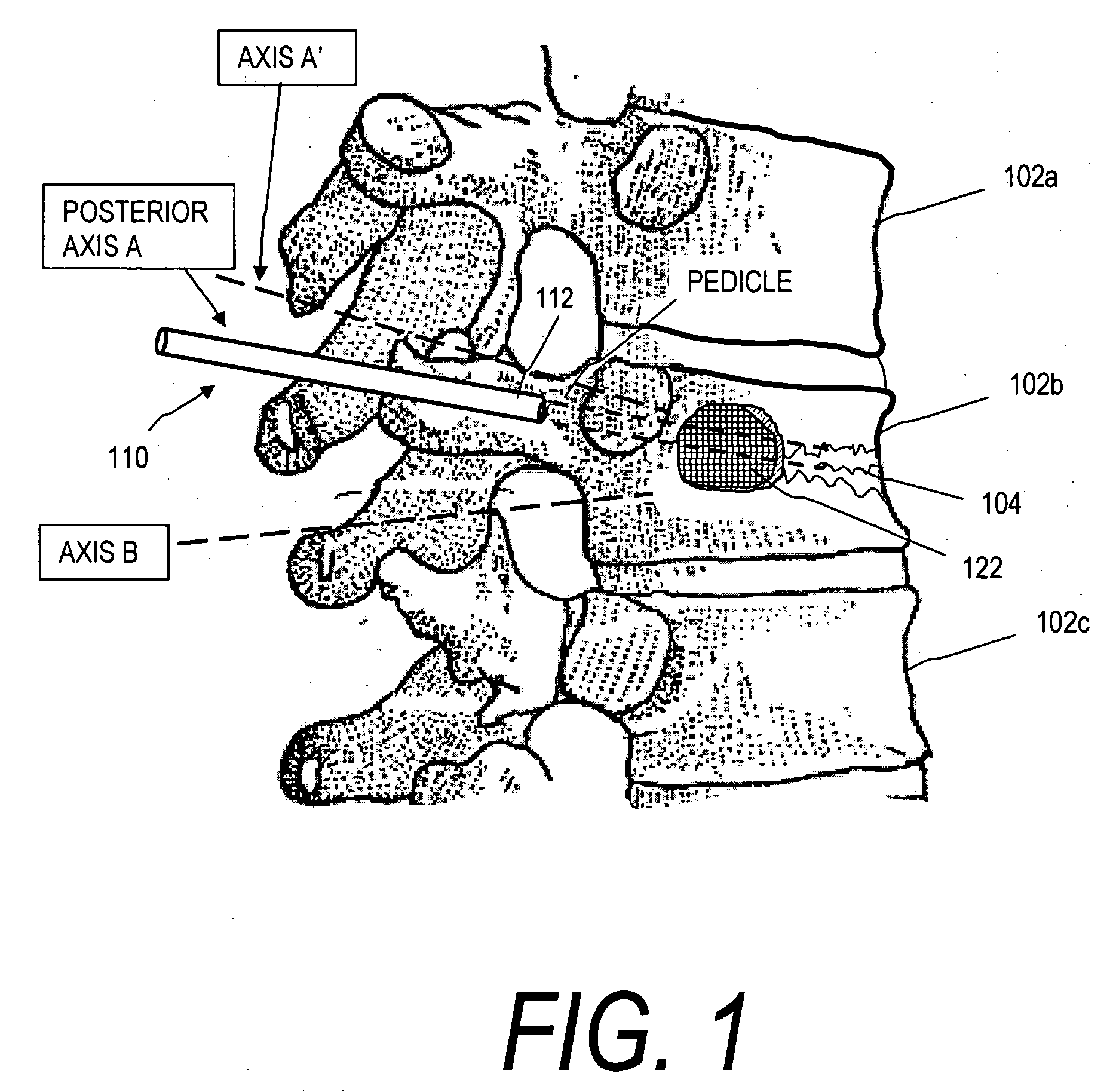
[0092]FIG. 1 illustrates a vertebral body 102b with a wedge vertebral compression fracture (VCF) 104. The stent deployment systems and methods disclosed herein are directed in some embodiments to safely introducing bone cement into cancellous bone to eliminate pain and to increase vertebral body height. Vertebral body 102a is susceptible to a VCF following treatment of the fractured vertebra 102b since biomechanical loading will be altered. More particularly, the stent deployment systems and methods disclosed herein include systems for treating an acute or older VCF and for preventing a future VCF in a spine segment. In particular, the systems are adapted for restoration of vertebral body height to thereby restore biomechanics of the affected spine segment.

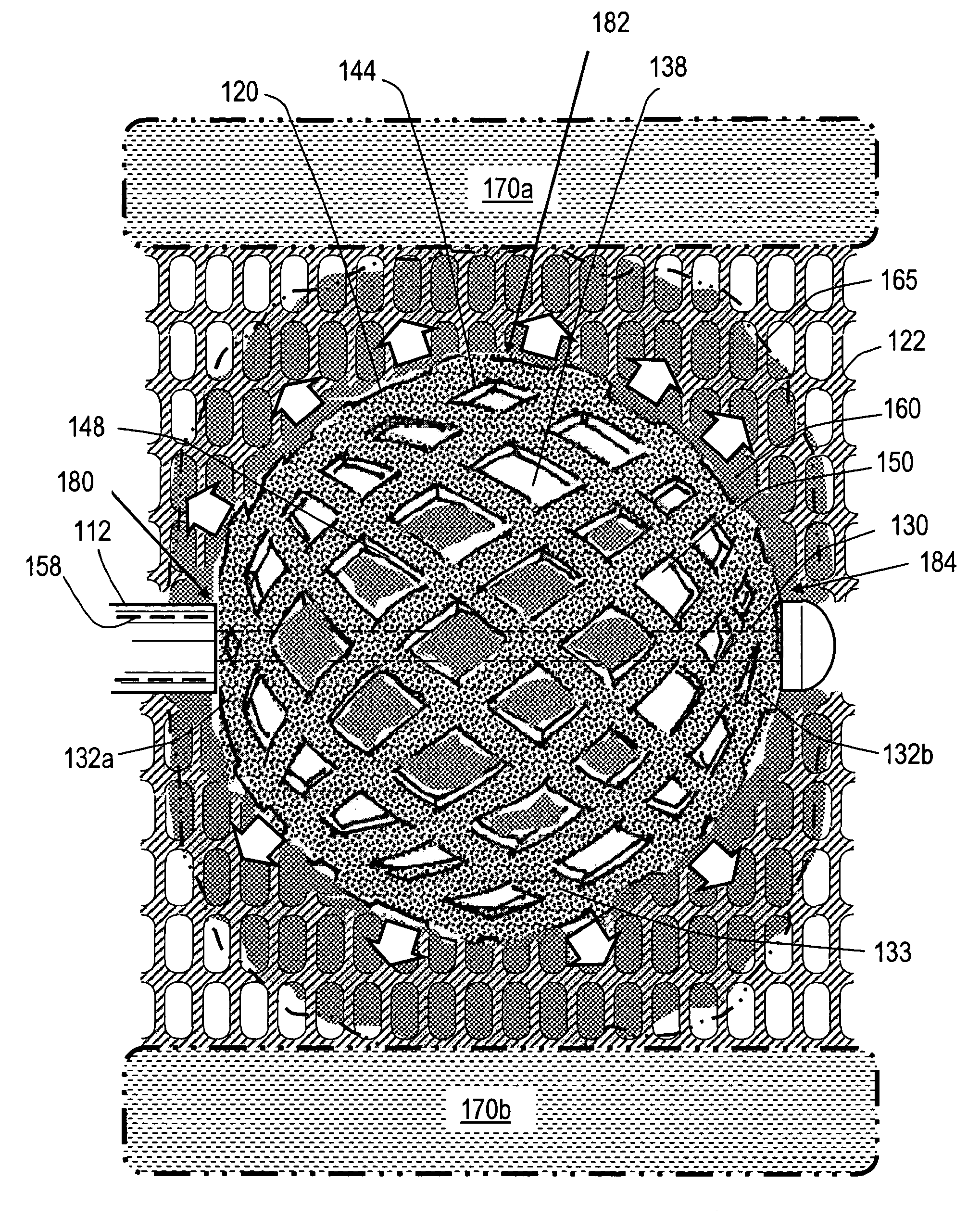
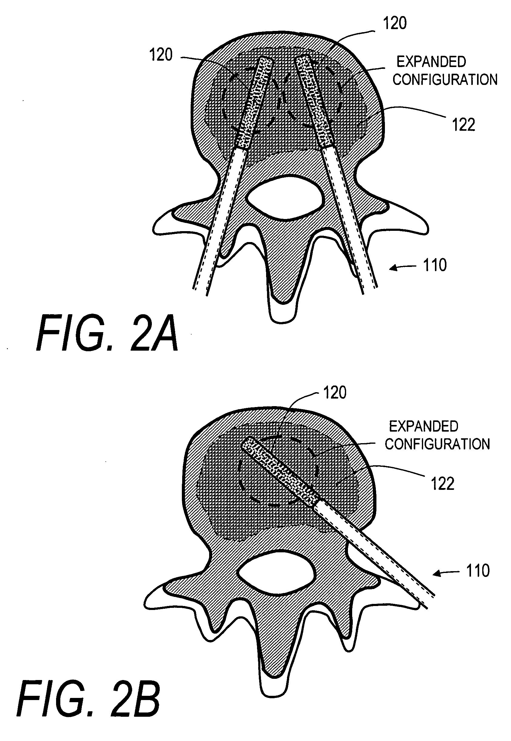
[0093]FIGS. 1, 2A and 2B illustrate one embodiment of a stent deployment system 100 comprising a probe or introducer 110 having an elongated shaft 112 that carries an expandable stent 120 (not shown in FIG. 1) at a distal end of ...


PUM


Abstract

Stent systems and methods for expanding and deploying stents in hard tissue such as bone, more particularly within a vertebral body. One exemplary method includes using a stent body that is coupled to a high speed rotational motor with the stent expandable and detachable from an introducer working end. In one embodiment, the stent is a deformable metal body with zig-zag type struts in an expanded configuration that carries diamond cutting particles bonded to the strut surfaces. The “spin” stent is rotated at high rpm's to remove cancellous bone from the deployment site together with irrigation and aspiration at the end of the probe that carries the stent. The stent may be expanded asymmetrically, such as with first and second balloons or by using an interior restraint, to apply vertical distraction forces to move apart the cortical endplates and support the vertebra in the distracted condition. The cancellous bone about the expanded stent as well as the interior of the stent can be filled with a bone cement, allograft or other bone graft material. In one method of use, the spin stent is designed and adapted for (i) treating a vertebral compression fracture (VCF) or for (ii) reinforcing an osteoporotic vertebral body.

Description

CROSS-REFERENCE TO RELATED APPLICATIONS [0001] This application claims priority to U.S. Provisional Application No. 60 / 638,970, filed Dec. 21, 2004, U.S. Provisional Application No. 60 / 640,137, filed Dec. 29, 2004, and U.S. Provisional Application No. 60 / 648,023, filed Jan. 28, 2005, the entire contents of which are hereby incorporated by reference in their entirety and should be considered a part of this specification. This application also incorporates by reference U.S. Provisional Application No. 60 / 626,701 filed Nov. 10, 2004, the contents of which are hereby incorporated herein in its entirety and should be considered a part of this specification.BACKGROUND OF THE INVENTION [0002] 1. Field of the Invention [0003] Embodiments of the present invention relate to systems and methods for treating hard tissues such as bones, and more particularly, to stent systems for treating fractured or osteoporotic vertebrae that provide for high speed rotational cutting of bone and implantation ...

Claims


Application Information

Patent Timeline
IPC IPC(8): A61F2/44
CPCA61B17/1617A61B17/1671A61B17/7098A61F2/44A61F2/4601
Inventor SHADDUCK, JOHNTRUCKAI, CSABA
Owner DFINE INC
Why Eureka
Try Eureka