Manufacturing method of heat conducting device

Active Publication Date: 2017-12-14
DELTA ELECTRONICS INC
View PDF23 Cites 29 Cited by
  • Summary
  • Abstract
  • Description
  • Claims
  • Application Information

AI Technical Summary

Benefits of technology

[0016]As mentioned above, the manufacturing method of the disclosure can form a continuous wick structure on the inner wall between the heat conducting element and the vapor chamber without undesired thermal resistance. Accordingly, the gaseous state working fluid can be rapidly transferred from the vapor chamber to each of the heat conducting elements without the obstruction of addi

Problems solved by technology

However, the wick structure is discontinuous at the welding portion of the heat pipe and the vapor chamber, so that the internal vapor space is not continuous.
This st

Method used


Image

  • Manufacturing method of heat conducting device
  • Manufacturing method of heat conducting device
  • Manufacturing method of heat conducting device

Examples


Embodiment Construction

[0023]The present disclosure will be apparent from the following detailed description, which proceeds with reference to the accompanying drawings, wherein the same references relate to the same elements.

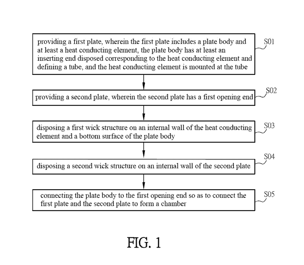
[0024]FIG. 1 is a schematic flow chart of a manufacturing method of a heat conducting device according to an embodiment of the disclosure.

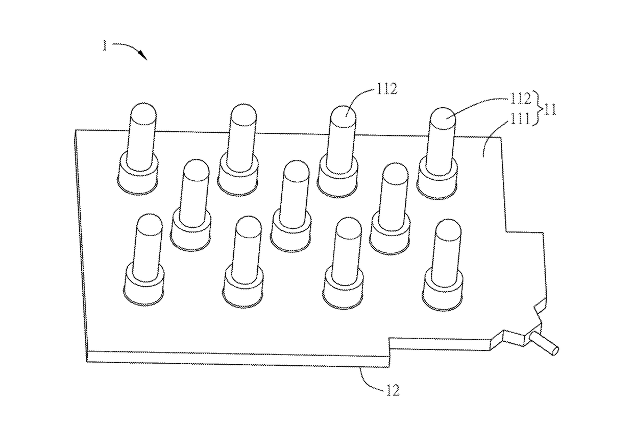
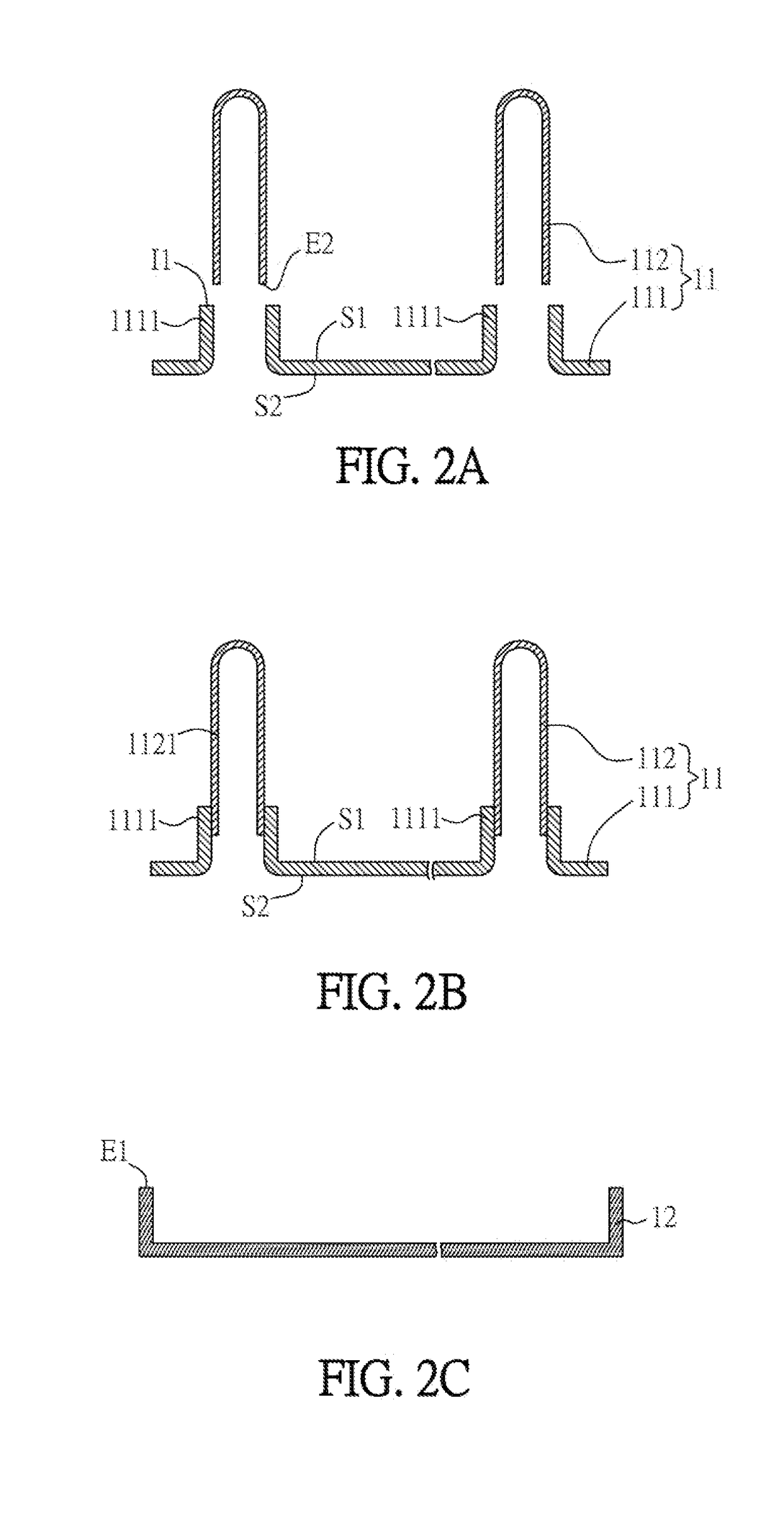
[0025]Referring to FIG. 1, the manufacturing method of a heat conducting device of the disclosure includes following steps: providing a first plate, which includes a plate body and at least a heat conducting element, wherein the plate body has at least an inserting end disposed corresponding to the heat conducting element and defining a tube, and the heat conducting element is mounted at the tube (step S01); providing a second plate, which has a first opening end (step S02); disposing a first wick structure on an internal wall of the heat conducting element and a bottom surface of the plate body (step S03); disposing a second wick structure on an i...


PUM

PropertyMeasurementUnit
Temperatureaaaaaaaaaa
Thicknessaaaaaaaaaa
Structureaaaaaaaaaa

Abstract

A manufacturing method of a heat conducting device includes following steps: providing a first plate, which includes a plate body and at least a heat conducting element, wherein the plate body has at least an inserting end disposed corresponding to the heat conducting element and defining a tube, and the heat conducting element is mounted at the tube; providing a second plate, which has a first opening end; disposing a first wick structure on an internal wall of the heat conducting element and a bottom surface of the plate body; disposing a second wick structure on an internal wall of the second plate; and connecting the plate body to the first opening end so as to connect the first plate and the second plate to form a chamber. Accordingly, the heat conducting device has a higher heat conducting efficiency.

Description

CROSS REFERENCE TO RELATED APPLICATIONS[0001]The non-provisional patent application claims priority to U.S. provisional patent application with Ser. No. 62 / 347,459 filed on Jun. 8, 2016. This and all other extrinsic materials discussed herein are incorporated by reference in their entirety.[0002]This Non-provisional application claims priority under 35 U.S.C. §119(a) on Patent Application No(s). 201710377130.0 filed in People's Republic of China on May 25, 2017, the entire contents of which are hereby incorporated by reference.BACKGROUND OF THE DISCLOSUREField of Disclosure[0003]The present disclosure relates to a manufacturing method of a heat conducting device.Related Art[0004]Heat pipes and temperature plates (or vapor chambers) are commonly used high performance heat conducting device having the features of high heat conducting efficiency, less weight, simple structure and free from electricity. Accordingly, the heat conducting device containing the heat pipes and vapor chambers...

Claims


Application Information

Patent Timeline
IPC IPC(8): F28D15/02F28D15/04H01L23/473F21K9/20
CPCF28D15/0275F28D15/046F21K9/20F28D15/0266H01L23/473F28D15/0233H01L21/4882H01L23/3672H01L23/3736H01L23/427B23P15/26Y10T29/49353Y10T29/49359
Inventor TAN, LI-KUANGLIN, SHIH-KANG
Owner DELTA ELECTRONICS INC
Why Eureka
Try Eureka