
Thermal electricity conversion based on the heat extracted from underground coal fires

a technology of thermal energy and coal fire, which is applied in the direction of electric vehicles, generators/motors, transportation and packaging, etc., can solve the problems of insufficient adaptability of technology and equipment, polluted air, land and water, and human health threats, and achieve high extraction efficiency of thermal energy of coal fire, high heat conduction speed of hot side, and high thermal energy extraction efficiency

Inactive Publication Date: 2020-01-30
CHINA UNIV OF MINING & TECH
View PDF6 Cites 3 Cited by
  • Summary
  • Abstract
  • Description
  • Claims
  • Application Information

AI Technical Summary

Benefits of technology

The invention is a system for generating power from heat that is based on direct attachment of thermoelectric chips onto a heat conduction container, resulting in a simple and efficient system. The thermoelectric chips have cold side radiator pipes, which increase the contact area with the heating media, refrigerants, and the chips, allowing for better utilization of thermal energy. The system also has a multi-loop bending design for the cooling water radiator, which increases the cooling area and improves power generation efficiency. These features make the system suitable for use in the coalfield fire area.

Problems solved by technology

The coal fire seriously threatens human health, resulting in a series of related diseases such as respiratory disease, skin cancer and heart disease; the harmful chemicals, such as mercury, selenium and other heavy metals, sulfides and PM2.5, which are released into the air and accumulated in a long term, will pollute air, land and water).
The impact of the coalfield field fire on the environment cannot be ignored, resulting in serious {circle around (1)} air pollution, where lots of heat, toxic and harmful gases and greenhouse gases are emitted into the atmosphere; {circle around (2)} water pollution, where acid-base compounds generated by combustion of the coal fire area are discharged in spring and mine water form from the earth surface along bedrock fissure water at valley mouths, cliffs and steeps, or constantly moved along the groundwater; {circle around (3)} destruction of ground vegetation, where the surface temperature of the coalfield fire area rises sharply to destroy the original physical structure and nature of the soil, while the sulfate and sulfur precipitated in the coalfield fire area increase the soil acidity, so that the sulfur content is increased and the vegetation cannot survive; and {circle around (4)} potential geological hazards, where the burned out area is formed after combustion of shallow coal seams, underground float coal, coal pillars and the like, thus changing the balanced state between the coal seam roof and the surrounding rocks, resulting in a large number of combustion fractures, collapse pits and the like on the ground while providing oxygen supply channels for combustion of the coal seams, and forming a vicious cycle of “combustion-collapse-combustion”; moreover, the soil and water retention capacity of the earth surface is dropped significantly, thereby easily leading to debris flow, landslides and other geological disasters.
However, the existing fire prevention theory, technology and equipment cannot fully adapt to the development of the subsurface fire.
The existing coal fire control techniques, which generally extinguish the fire by grouting or injecting liquid nitrogen to prevent the spreading of coal fire but cannot block the energy accumulation of the subsurface fire, are mostly palliatives without good effect.

Method used


Image

  • Thermal electricity conversion based on the heat extracted from underground coal fires
  • Thermal electricity conversion based on the heat extracted from underground coal fires
  • Thermal electricity conversion based on the heat extracted from underground coal fires

Examples


Embodiment Construction

[0021]The invention will be further described in detail as follows with reference to the drawings.

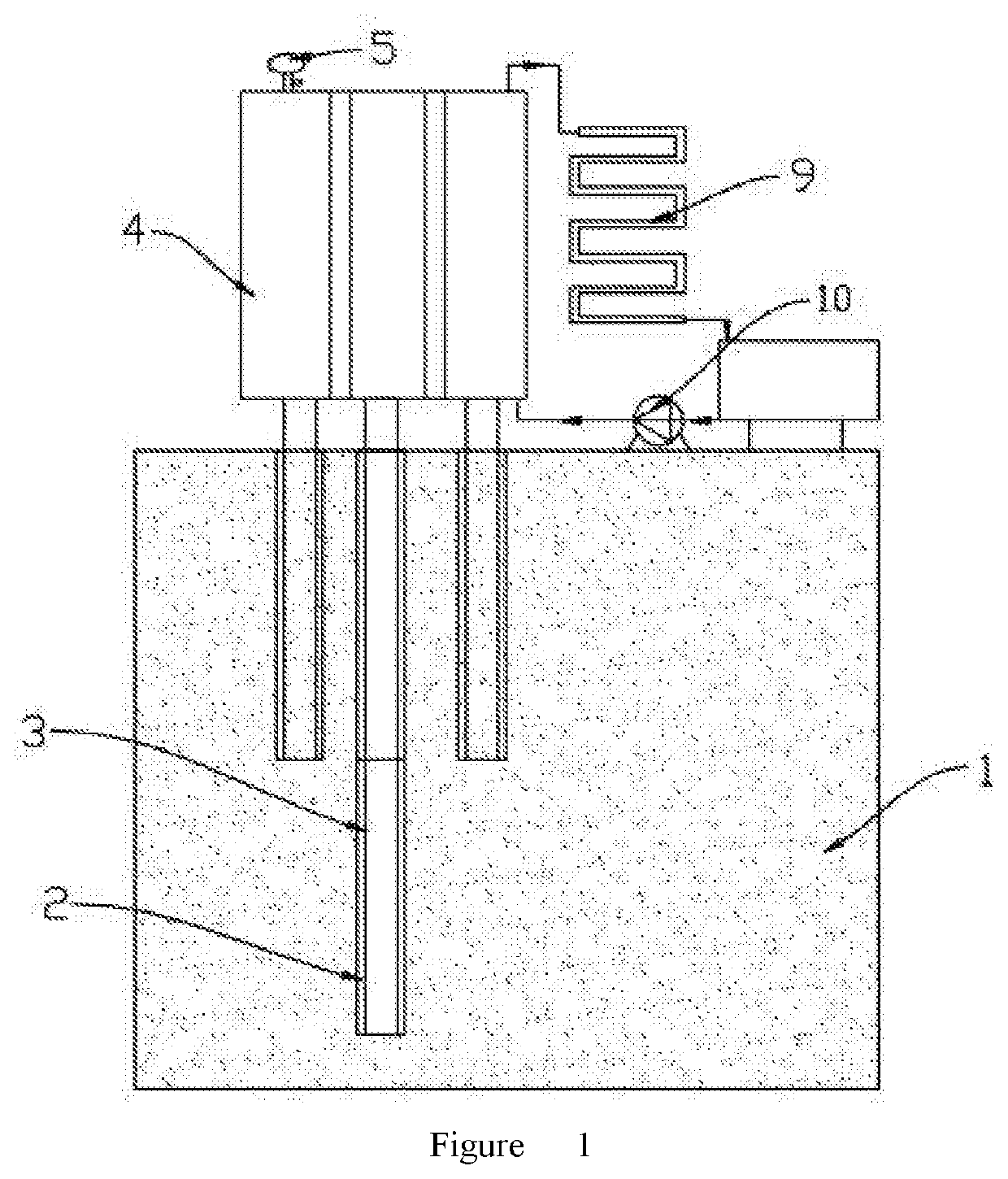
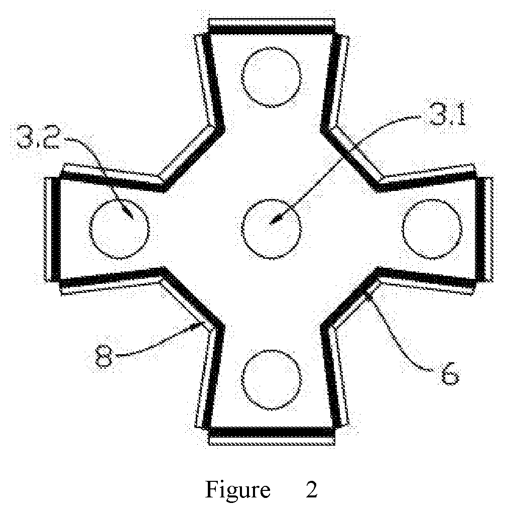
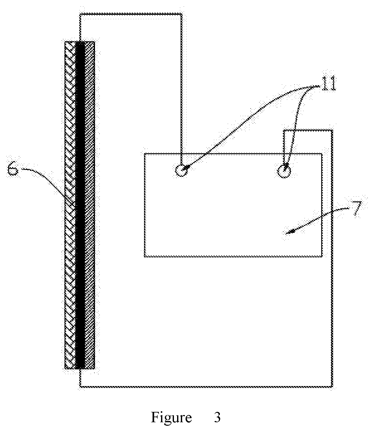
[0022]With reference to the drawings, a thermal electricity conversion based on the heat extracted from underground coal fires is provided, comprising a coalfield fire area 1, and coalfield drill holes 2 provided on the coalfield fire area 1. Underground heat conduction pipelines 3 with enclosed bottoms are provided in the coalfield drill holes 2, one end of each of the underground heat conduction pipelines 3 is located in the underground for absorbing heat and the other end thereof is provided with a heat conduction container 4 communicated thereto; the heat conduction container 4 is provided with a pressure relief device 5 thereon and further comprises thermoelectric power generation chip sets 6 for generating electricity and a storage battery 7 connected to the thermoelectric power generation chip sets 6 for storing electricity; the thermoelectric power generation chip sets 6, having...


PUM


Abstract

Thermal electricity conversion based on the heat extracted from underground coal fires, comprising a coalfield fire area (1), coalfield drill holes (2), underground heat conduction pipelines (3) and a heat conduction container (4) which is provided with a pressure relief device (5) thereon and further comprises thermoelectric power generation chip sets (6) and a storage battery (7), wherein the thermoelectric power generation chip sets (6), having cold-side radiator pipes (8) provided on outer sides thereof, are provided on an outer side wall of the heat conduction container (4). The thermoelectric power generation chip sets in the invention are directly attached on the heat conduction container, so that the system is simple in structure without redundant components and high in heat conduction efficiency. The thermoelectric power generation chip sets, having the cold side radiator pipes on outermost layers thereof, are surface mounted so that the contact area among heating media, refrigerants and the thermoelectric power generation chip sets, and the thermal energy of the subsurface fire may be utilized efficiently. The thermoelectric power generation system is simple in process and may be well adapted to the engineering operating environment in the coalfield fire area.

Description

FIELD OF INVENTION[0001]The present belongs to the technical field of heat recovery in coalfield fire area, and more particularly relates to thermal electricity conversion based on the heat extracted from underground coal fires.BACKGROUND OF THE INVENTION[0002]Subsurface fire (SF) is a general term for coalfield fire and coal mine fire formed by the coal seam resulted from human factors or spontaneous combustion, and is commonly occurred in China, the United States, Australia, India, Indonesia and other countries, resulting in: {circle around (1)} loss of a large number of coal resources (the global loss is about 1 billion tons / year while the current coal consumption in the whole world is 8 billion tons / year); {circle around (2)} threatening the mining safety (the raw coal mining process and the mining safety are seriously affected by the subsidence areas and the burned out areas resulted from combustion of the subsurface fire, resulting in blockage of resources or even mining accid...

Claims


Application Information

Patent Timeline
IPC IPC(8): H02N11/00H01L35/30H02J7/32
CPCH01L35/30H02N11/002H02J7/32H02J7/34H10N10/13
Inventor ZHOU, FUBAOSU, HETAOSHI, BOBOQI, HAININGLI, JINSHI
Owner CHINA UNIV OF MINING & TECH
Learn More