Devices to prevent spinal extension

a technology of spinal cord extension and device, applied in the field of spinal cord surgery, can solve the problems of low back pain in some patients, and achieve the effects of preventing pain and other complications, inhibiting full extension, and limiting spinal flexion, rotation and/or lateral bending

Inactive Publication Date: 2005-12-29
NUVASIVE
View PDF2 Cites 436 Cited by
  • Summary
  • Abstract
  • Description
  • Claims
  • Application Information

AI Technical Summary

Benefits of technology

[0008] This invention resides in apparatus for inhibiting full extension between upper and lower vertebral bodies, thereby preventing pain and other complications associated with spinal movement. In the preferred embodiment, the invention provides a generally transv

Problems solved by technology

Extension of the spine increases pressure on the facet joints, and this pressure may l

Method used


Image

  • Devices to prevent spinal extension
  • Devices to prevent spinal extension
  • Devices to prevent spinal extension

Examples


Embodiment Construction

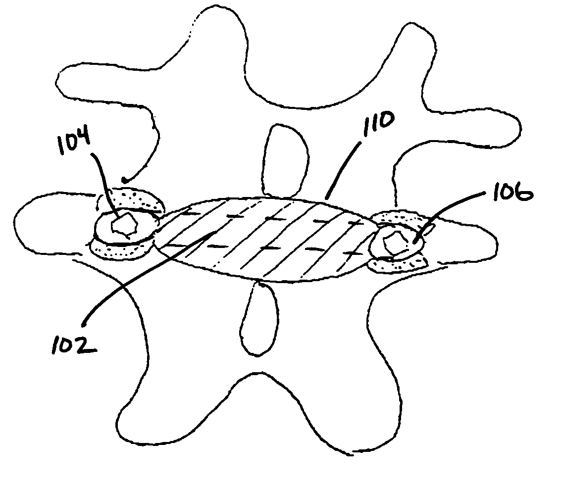
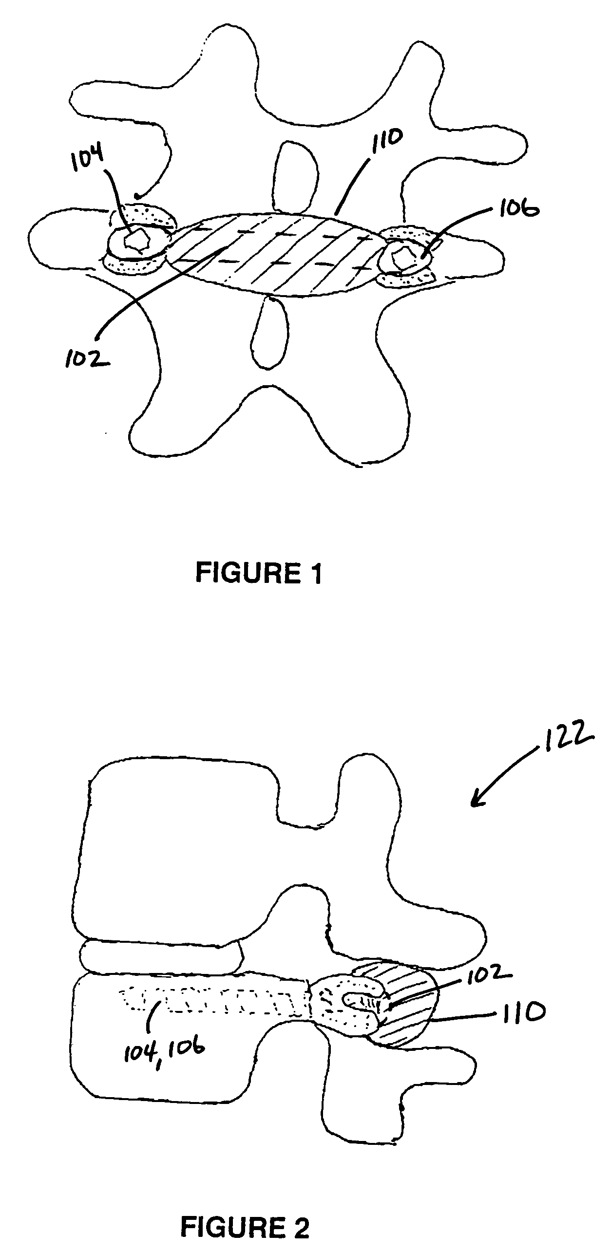
[0027] This invention minimizes or eliminates spinal extension through the use of a generally transverse member, preferably anchored at two points on the same vertebra to prevent adjacent vertebrae from coming closer together. The preferred embodiment, shown in FIGS. 1 and 2, uses a sleeved rod 102 or cable placed transversely between pedicle screws 104, 106. The sleeve 110 impinges upon the spinous processes and lamina of the vertebra 120 holding the pedicle screws and the spinous processes and lamina of the vertebra 122 directly above the vertebra with the pedicle screws 104, 106. As such, the device prevents spinal extension at the level it is inserted. For example, the device would be placed between pedicle screws at L4 to prevent extension of the spine between L3 and L4.

[0028] The sleeve could be made of any compressible or resilient material that has cushion-like properties and sufficient tensile strength. For example, natural and synthetic rubbers, elastomers, encased gels a...


PUM


Abstract

This invention resides in an apparatus for inhibiting full extension between upper and lower vertebral bodies, thereby preventing pain and other complications associated with spinal movement. In the preferred embodiment, the invention provides a generally transverse member extending between the spinous processes and lamina of the upper and lower vertebral bodies, thereby inhibiting full extension. Various embodiments of the invention may limit spinal flexion, rotation and/or lateral bending while preventing spinal extension. In the preferred embodiment, the transverse member is fixed between two opposing points on the lower vertebral body using pedicle screws, and a cushioning sleeve is used as a protective cover. The transverse member may be a rod or cable, and the apparatus may be used with a partial or full artificial disc replacement. To control spinal flexion, rotation and/or lateral bending one or more links may be fastened to an adjacent vertebral body, also preferably using a pedicle screw. Preferably a pair of opposing links are used between the upper and lower vertebral bodies for such purposes.

Description

CROSS REFERENCES TO RELATED APPLICATIONS [0001] The present application is a continuation of commonly owned and co-pending U.S. patent application Ser. No. 10 / 444,883 filed May 23, 2003, the complete disclosure of which is hereby incorporated herein by reference in its entirety for all purposes. Additionally, the present application claims benefit under 35 U.S.C. § 119(e) from U.S. Provisional Application Ser. No. 60 / 383,041, filed on May 24, 2002, and U.S. Provisional Application Ser. No. 60 / 385,171, filed May 31, 2002, the entire contents of which are hereby expressly incorporated by reference into this disclosure as if set forth fully herein.BACKGROUND OF THE INVENTION [0002] I. Field of the Invention [0003] This invention relates generally to spine surgery and, in particular, to apparatus for preventing spinal extension. [0004] II. Description of the Related Art [0005] Extension of the spine increases pressure on the facet joints, and this pressure may lead to low back pain in s...

Claims


Application Information

Patent Timeline
IPC IPC(8): A61B17/56A61B17/70A61F2/44
CPCA61B17/7007A61B17/7008A61B17/7023A61B17/7025A61F2002/443A61B17/7032A61B17/7044A61B17/7067A61B17/7028
Inventor FERREE, BRET A.
Owner NUVASIVE
Why Eureka
Try Eureka