Devices, systems and methods for treating disorders of the ear, nose and throat

Active Publication Date: 2006-05-04
ACCLARENT INC
View PDF30 Cites 529 Cited by
  • Summary
  • Abstract
  • Description
  • Claims
  • Application Information

AI Technical Summary

Benefits of technology

[0016] Still further in accordance with the invention, there is provided a method for dilating a Eustachian tube in a human or animal subject, said method domprising the steps of: A) providing a a guide member (e.g., a guidewire) that is insertable through the nose and is advanceable into the Eustachian tube through the pharyngeal ostium of the Eustachian tube and a dilator that is advanceable over the guidewire and useable to dilate the Eustachian tube; B) inserting the guidewire into the Eustachian tube; C) advancing the dilator over the guide member and into the Eustachian tube; and D) using the dilator to dilate the Eustachian tube. In some embodiments of this method, the

Problems solved by technology

Often patients complain of the post-operative pain and bleeding associated with the procedure, and a significant subset of patients remain symptomatic even after multiple surgeries.
Since FESS is considered an option only for the most severe cases (those showing abnormalities under CT scan), a large population of patients exist that can neither tolerate the prescribed medications nor be considered candidates for surgery.
To date, there is no mechanical therapy offered for these patients, and even though they may fail pharmaceutical therapies, no other course of action is indicated.
This leaves a large population of patients in need of relief, unwilling or afraid to take steroids, but not sick enough to qualify for surgery.
These techniques were not reported to be ueable for the treatment of sinus ostia that has not previously been surcically altered or ostia of sinuses other than the easily accessible frontal sinuses.
The techniques described in these publications have not been widely adopted by ENT surgeons, possibly due to the fact that they lacked important novel improvements and modifications as described in this patent application and prior U.S. patent application Ser. Nos. 10/829,917, 10/912,578 and 10/944,270, of which this application is a continuation-in-part.
The patent does not disclose device designs and methods for

Method used


Image

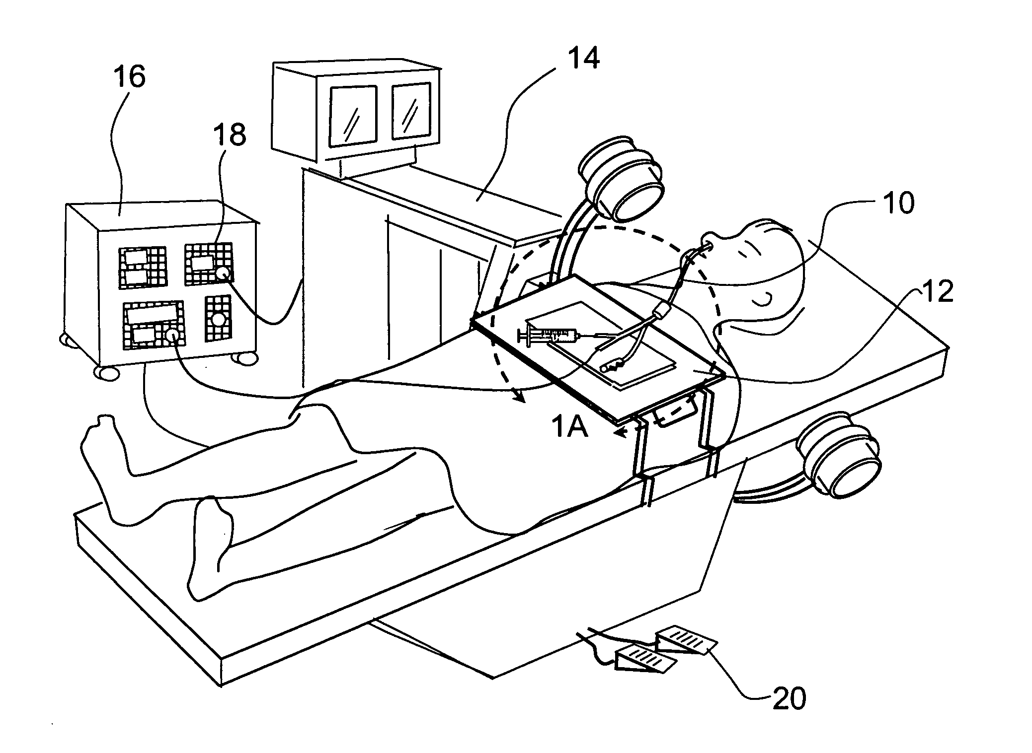
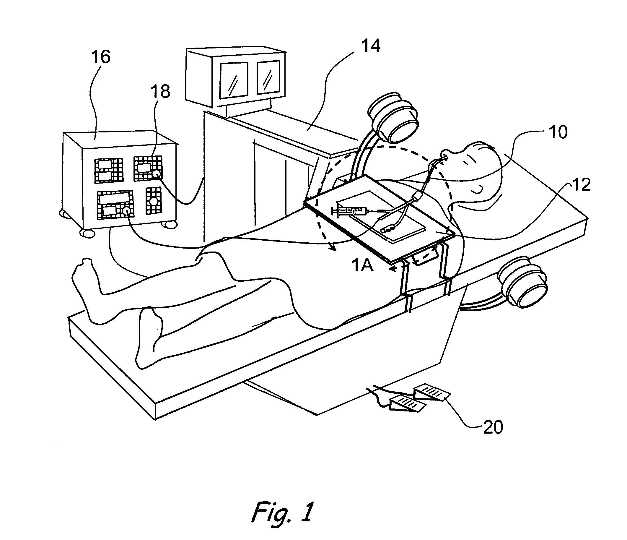
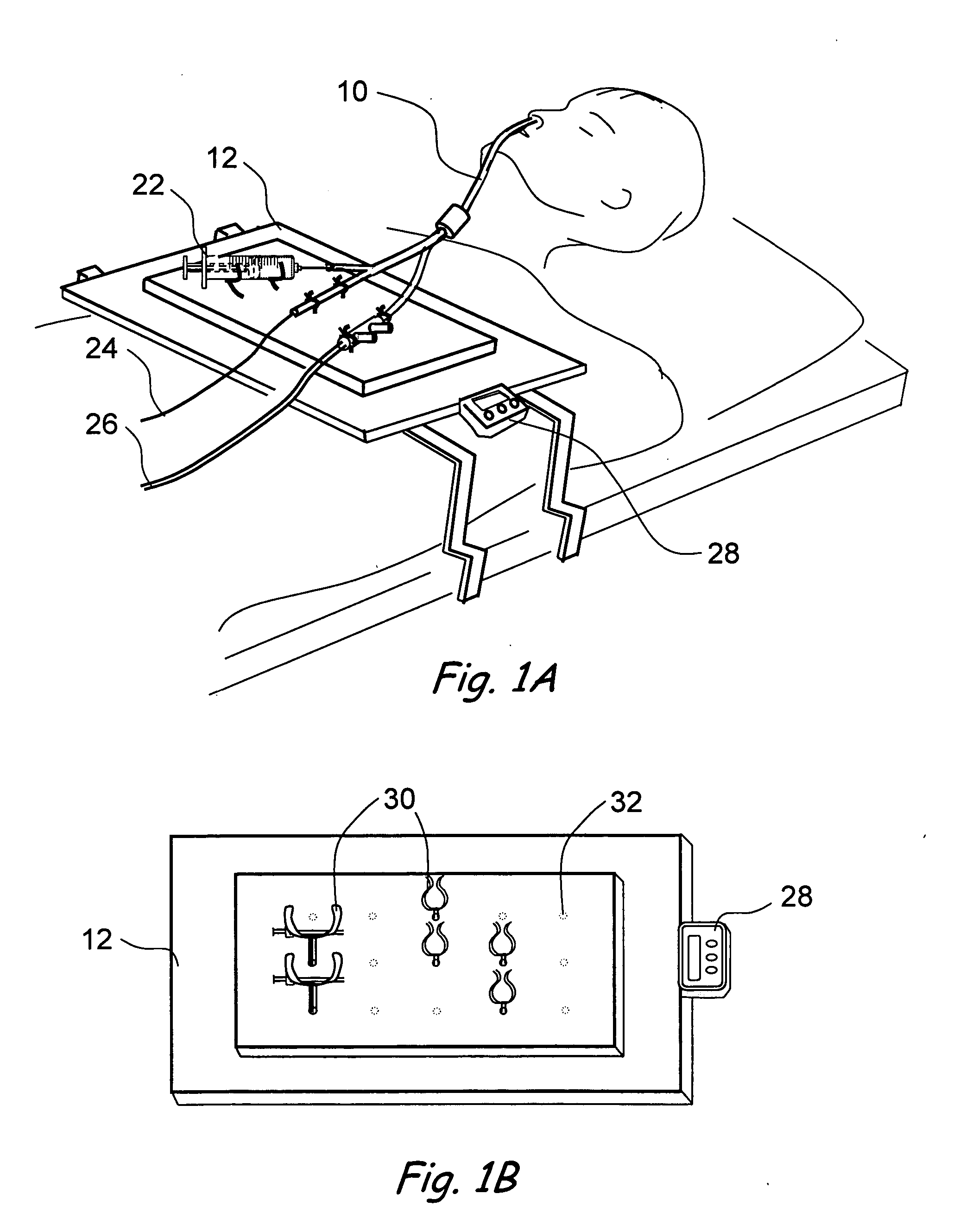
  • Devices, systems and methods for treating disorders of the ear, nose and throat
  • Devices, systems and methods for treating disorders of the ear, nose and throat
  • Devices, systems and methods for treating disorders of the ear, nose and throat

Examples


second embodiment

[0141]FIG. 8 shows a perspective view of a guide catheter comprising a straight hypotube. Guide catheter 700 comprises a hypotube 702. Proximal end of hypotube 702 may comprise a threaded luer 704. Hypotube 702 encloses a tubular liner 706 that protrudes from the distal end of hypotube 702. Suitable materials for constructing tubular liner 706 are PTFE, Nylon, PEEK etc. Distal region of tubular liner 706 is covered with a tubular element 708. Tubular element 708 may be constructed of suitable materials such as Pebax, HDPE, Nylon etc. and may comprise a braid. Proximal end of tubular element 708 may be bonded to distal end of hypotube 702 or may overlap distal region of hypotube 702. In one embodiment, distal region of tubular element 708 comprises a bent or angled region. In another embodiment, stiffness of tubular element 708 varies along the length of tubular element 708. Tubular element 708 may comprise a radio-opaque marker band 710 near distal end of tubular element 708. FIG. 8...

first embodiment

[0149]FIG. 11A shows a perspective view of a dual balloon catheter that can be used to perform a diagnostic or therapeutic procedure. Catheter 1000 comprises a catheter shaft 1002 and a proximal balloon 1004 and a distal balloon 1006 located on catheter shaft 1002. A variety of diagnostic or therapeutic modules may be located in the inter-balloon region 1008 located between proximal balloon 1004 and distal balloon 1006. Examples of such diagnostic or therapeutic modules are dilating or occluding balloons, dilating stents, suction or irrigation devices, needles, polypectomy tools, energy emitting devices like ablation devices, laser devices, image-guided devices containing sensors or transmitters, imaging devices, endoscopes, tissue modifying devices like cutters, biopsy devices, devices for injecting diagnostic or therapeutic agents, lavage devices, drug delivery devices such as substance eluting devices, substance delivery implants etc. etc. A catheter hub 1010 is located on the pr...


PUM


Abstract

Sinusitis, mucocysts, tumors, infections, hearing disorders, choanal atresia, fractures and other disorders of the paranasal sinuses, Eustachian tubes, Lachrymal ducts and other ear, nose, throat and mouth structures are diagnosed and/or treated using minimally invasive approaches and, in many cases, flexible catheters as opposed to instruments having rigid shafts. Various diagnostic procedures and devices are used to perform imaging studies, mucus flow studies, air/gas flow studies, anatomic dimension studies and endoscopic studies. Access and occluding devices may be used to facilitate insertion of working devices such asendoscopes, wires, probes, needles, catheters, balloon catheters, dilation catheters, dilators, balloons, tissue cutting or remodeling devices, suction or irrigation devices, imaging devices, sizing devices, biopsy devices, image-guided devices containing sensors or transmitters, electrosurgical devices, energy emitting devices, devices for injecting diagnostic or therapeutic agents, devices for implanting devices such as stents, substance eluting or delivering devices and implants, etc.

Description

RELATED APPLICATION [0001] This application is a continuation-in-part of 1) U.S. patent application Ser. No. 10 / 829,917 entitled “Devices, Systems and Methods for Diagnosing and Treating Sinusitis and Other Disorders of the Ears, Nose and / or Throat” filed on Apr. 21, 2004, 2) U.S. patent application Ser. No. 10 / 912,578 entitled “Implantable Device and Methods for Delivering Drugs and Other Substances to Treat Sinusitis and Other Disorders” filed on Aug. 4, 2004 and 3) U.S. patent application Ser. No. 10 / 944,270 entitled “Apparatus and Methods for Dilating and Modifying Ostia of Paranasal Sinuses and Other Intranasal or Paranasal Structures” filed on Sep. 17, 2004, the entireties of each such parent application being expressly incorporated herein by reference.FIELD OF THE INVENTION [0002] The present invention relates generally to medical devices, systems and methods and more particularly to minimally invasive devices, systems and methods for treating sinusitis and other ear, nose & ...

Claims


Application Information

Patent Timeline
IPC IPC(8): A61M29/00A61F2/958
CPCA61B10/06A61F11/002A61B17/12045A61B17/12104A61B17/12136A61B17/1604A61B17/1608A61B17/1679A61B17/1688A61B17/24A61B17/32002A61B17/32075A61B17/3478A61B19/0256A61B19/5212A61B19/5244A61B2017/00247A61B2017/003A61B2017/320004A61B2017/3486A61B2017/3488A61B2018/00392A61B2019/025A61B2019/0255A61B2019/204A61B2019/5251A61F2/958A61F2250/0067A61M25/007A61M25/10A61M2025/105A61M2025/1052A61B5/065A61B17/1204A61B90/16A61B34/20A61B90/361A61B50/13A61B50/15A61B50/20A61B2034/2051A61F11/202
Inventor CHANG, JOHN Y.MAKOWER, JOSHUAVRANY, JULIA D.LAMSON, THEODORE C.WALKE, AMRISH JAYPRAKASH
Owner ACCLARENT INC
Why Eureka
Try Eureka