Camera having a liquid crystal display device

a liquid crystal display and camera technology, applied in the field of cameras having liquid crystal display devices, can solve the problems of reducing the transmittance of light, dark transmission display, and the inability to view the display of target patterns or the like on the liquid crystal display panel, so as to improve the efficiency of emitting light and reduce the intensity of ligh

Inactive Publication Date: 2005-01-25
CITIZEN WATCH CO LTD
View PDF14 Cites 59 Cited by
  • Summary
  • Abstract
  • Description
  • Claims
  • Application Information

AI Technical Summary

Benefits of technology

Further, the intensity of light of the light source part which reaches the liquid crystal display panel decreases in the case where the polarization separating device is simply disposed between the liquid crystal display panel and the light source part as compared to the case where the polarization separating device is not provided. Therefore, the reflection type polarizer is used as the polarization separating device to emit a linearly polarized light to the liquid crystal layer, and the component reflected toward the light source part is returned again to the reflection type polarizer, by cancelling its pola...

Problems solved by technology

Further, in a liquid crystal display panel having a liquid crystal layer composed of a twisted nematic (TN) liquid crystal or a super twisted nematic (STN) liquid crystal sandwiched between the pair of transparent substrates, it is necessary to dispose polarizers on both sides thereof, which decreases the transmittance of light, resulting in a dark transmission display.
Furthermore, when the environment where the camera is used is dark, the display of the target pattern or t...

Method used


Image

  • Camera having a liquid crystal display device
  • Camera having a liquid crystal display device
  • Camera having a liquid crystal display device

Examples


first embodiment

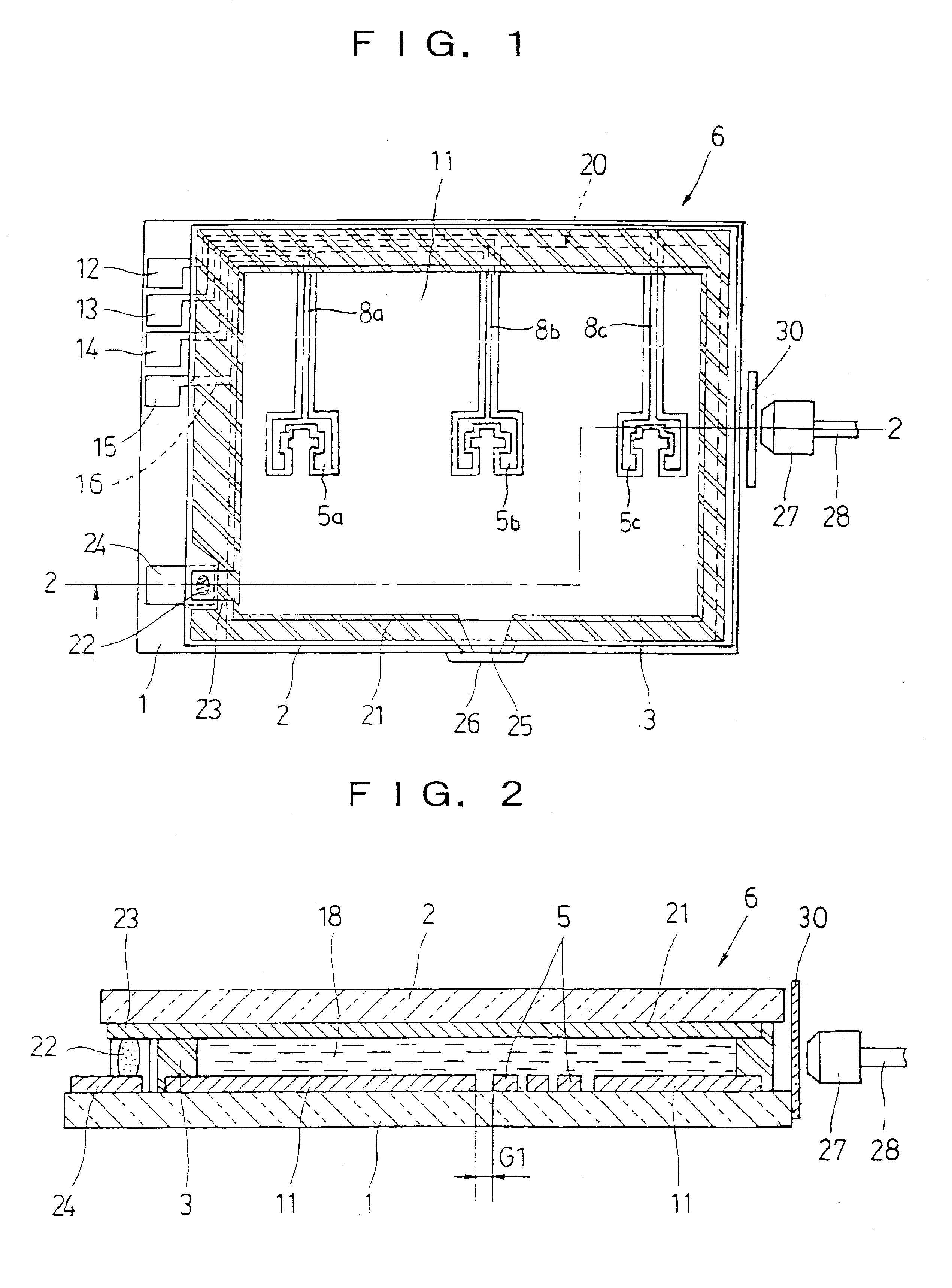
First, the first embodiment of a liquid crystal display device according to the invention is explained with reference to FIG. 1 to FIG. 9.

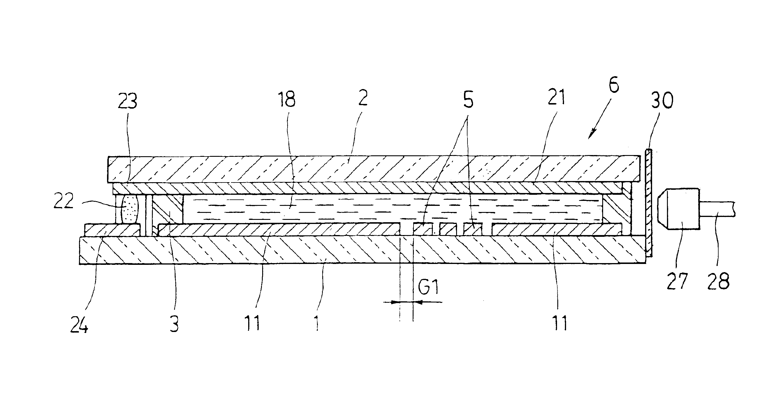
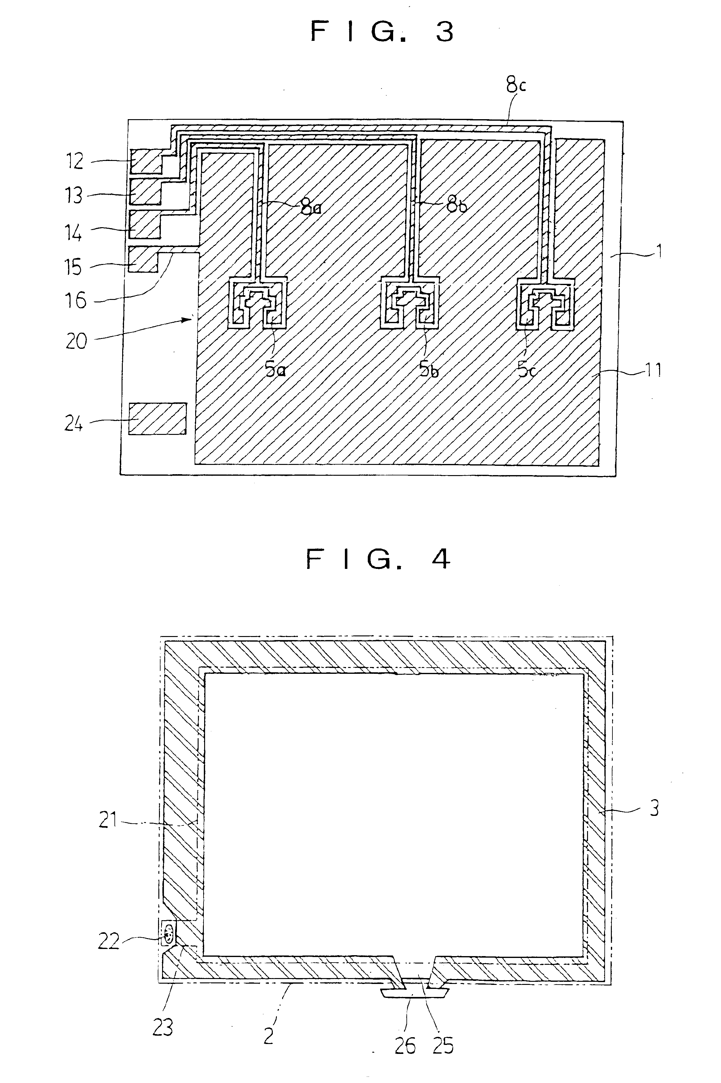
FIG. 1 is a plane view of a liquid crystal display panel and a light source part of the liquid crystal display device, FIG. 2 is a schematic cross-sectional view taken along a line 2—2 in FIG. 1, FIG. 3 is a plane view of a first substrate formed with a signal electrode on the upper surface thereof, FIG. 4 is a plane view of a sealing part provided between the first substrate and a second substrate, and FIG. 5 is a plane view of the second substrate formed with a counter electrode on the lower surface thereof.

With these drawings, the structure of the liquid crystal display panel of this embodiment is explained first.

In a liquid crystal display panel 6, as shown in FIG. 1 and FIG. 2, a first substrate 1 formed with a signal electrode 20 and a second substrate 2 formed with a counter electrode 21 on one surface, respectively, are coupled together, w...


PUM

PropertyMeasurementUnit
Widthaaaaaaaaaa
Transmissionaaaaaaaaaa
Strengthaaaaaaaaaa

Abstract

A liquid crystal display panel in which a signal electrode provided on a first substrate (1), a counter electrode provided on a second substrate (2), and a liquid crystal layer (18) between the substrates, and which carries out display without polarizers by changing the degree of transmission and scattering by means of a voltage applied to a pixel part. A light source part (27) is provided along the periphery of both substrates (1, 2), and a polarization separating device (30) is provided between the liquid crystal panel and the light source part (27).

Description

BACKGROUND OF THE INVENTION1. Field of the InventionThe present invention relates to a liquid crystal display device and, more specifically, to a liquid crystal display device in which almost the entire display area is brought into a transparent state for a condition behind it to be clearly viewed, so that only a specific pattern isolated in the display area is displayed in a scattering state.Further, the invention specifically relates to a liquid crystal display device which is installed in a finder optical system of a camera to be suitable for displaying a target pattern for autofocus in a finder visual field.2. Description of the Related ArtA liquid crystal display device using a liquid crystal display panel (LCD) has an advantage of thin-profile, light weight and, additionally, an extremely low power consumption, and thus it has been used as displays of wide-ranging devices including various kinds of portable electronic devices such as electronic calculators, cellular phones, wr...

Claims


Application Information

Patent Timeline
IPC IPC(8): G02F1/1335G02F1/1334G02F1/13G02F1/1343H04N5/232G02F1/1339G02F1/1333G02F1/13357
CPCG02F1/1334G02F1/13362G02F1/133615G02F1/1335
Inventor SEKIGUCHI, KANETAKAHASHIMOTO, NOBUYUKIHOSHINO, KOICHIKIKUCHI, MASAMI
Owner CITIZEN WATCH CO LTD
Why Eureka
Try Eureka