Method and relaxable distracters for in-situ formation of intervertebral disc prosthesis

a technology of intervertebral discs and distraction devices, which is applied in the field of surgical devices and procedures, can solve the problems of loss of some or all of the load support and articulation capabilities, complicated mechanical structures that are therefore expensive, and difficulty in proper installation

Inactive Publication Date: 2008-05-15
SYBERSPINE
View PDF2 Cites 223 Cited by
  • Summary
  • Abstract
  • Description
  • Claims
  • Application Information

AI Technical Summary

Benefits of technology

[0010]The method of the invention is to distract adjacent vertebrae from which the interposed and damaged nuclear material can been removed, leaving the annulus fibrosis intact, inject a curable polymer into the disc space around the distracter and against the vertebrae with the distracter still in position distracting the vertebrae, cure the polymer to a semi-rigid, pliable, elas...

Problems solved by technology

Consequently, the disc loses some or all of its load supporting and articulation capabilities, the load forces may become distributed improperly on the vertebrae and the nucleus pulposus may press against nerve roots causing pain.
One difficulty with many such devices is that they are complicated mechanical structures that are therefore expensive and they are difficult to properly install.
However, a problem and complication with these disc replacement devices is that, in order to install the disc replacement, the adjacent vertebrae must be distracted to provide a pro...

Method used


Image

  • Method and relaxable distracters for in-situ formation of intervertebral disc prosthesis
  • Method and relaxable distracters for in-situ formation of intervertebral disc prosthesis
  • Method and relaxable distracters for in-situ formation of intervertebral disc prosthesis

Examples


Embodiment Construction

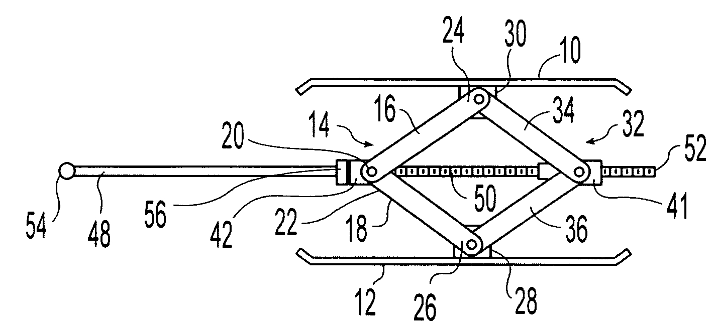
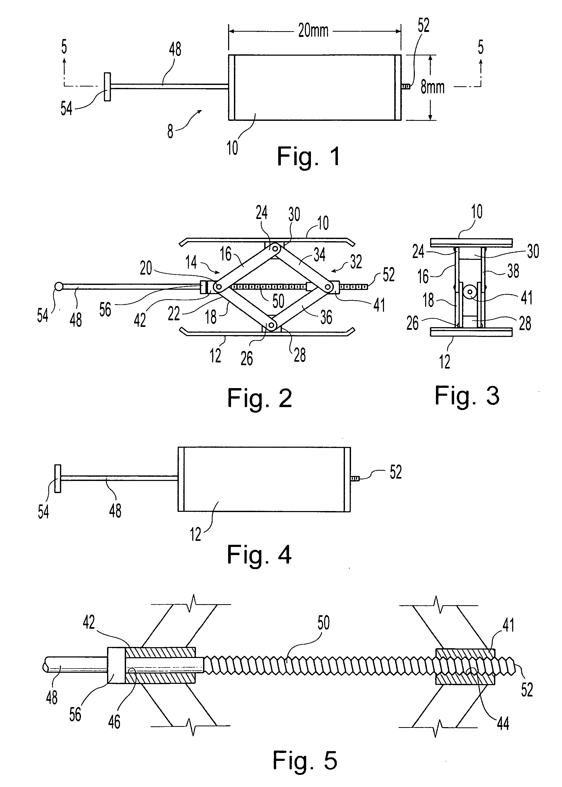
[0036]FIGS. 1-5 illustrate an inter-body distracter 8 embodying the invention and capable of use in practicing the method of the invention. Two, longitudinally opposite, support feet 10 and 12 face longitudinally outwardly for engaging the surface of the adjacent bodies that are to be distracted. In the method of the invention those bodies are vertebrae but the distracter can be used in other environments. A first pair 14 of links 16 and 18 are pivotally joined together at their proximal, engaging ends 20 and 22. Their respective distal ends 24 and 26 are each pivotally joined to a different one of the feet 10 and 12 at respective foot bearings 28 and 30 that are fixed to the support feet 10 and 12. A second, mirrored pair 32 of links 34 and 36 are laterally spaced from the first pair 14 of links 16 and 18.

[0037]On the opposite side of the foot bearings 28 and 30 are two more laterally spaced pairs of links that are pivotally connected together and to the feet 10 and 12 in the same ...


PUM

PropertyMeasurementUnit
Forceaaaaaaaaaa
Pressureaaaaaaaaaa
Diameteraaaaaaaaaa

Abstract

A method and a distracter for replacing a removed, intervertebral disc with a prosthesis. An inter-body distracter is inserted within the intervertebral space between adjacent vertebrae, the vertebrae are distracted and are supported by the distracter. A fluid, curable polymer is injected into the intervertebral space and around the distracter and then the polymer is cured to a semi-rigid, pliable, elastically deformable state. The distracter is then disabled from supporting compressive forces applied by the vertebrae and remains in place. The preferred distracter is a scissors jack having intermediate bearings joined by links to support feet. One of the bearings has a threaded lateral bore and the second bearing has a lateral bore. A rod extends through the bores and has a threaded portion extending from a first end of the rod and threadedly engaging the threaded bearing. The inside diameter of the second bore is greater than the outside diameter of the threaded portion of the rod so the rod is axially slidable through the second bore. A thrust bearing is fixed on the threaded rod and positioned laterally outwardly of the second bearing for forcing the second bearing laterally toward the first bearing upon rotation of the rod in one direction and for permitting the rod to be withdrawn from the bearing by rotating the rod in the opposite direction and disengaging it from the first bearing. Alternative distracters are also disclosed.

Description

BACKGROUND OF THE INVENTION[0001]1. Field Of The Invention[0002]This invention relates generally to surgical devices and procedures and more particularly relates to devices and a procedure for replacement of and / or augmentation of intervertebral disc nucleus in the spine.[0003]2. Description Of The Related Art[0004]The vertebral column or spine provides flexible mechanical support and comprises a series of vertebrae having adjacent vertebrae separated from each other by an intervertebral disc. Each disc consists of an annulus fibrosus forming an envelope surrounding an inner nucleus pulposus. The annulus fibrosus, while flexible, has a relatively small elasticity. The nucleus pulposus is a viscous fluid that, when contained in the annulus fibrosus, allows the disc to function as a semi-rigid, pliable, cushion. The disc allows relative articulation of adjacent vertebrae and elastically supports axial forces.[0005]Disc degeneration commonly occurs as a result of aging or injury. The a...

Claims


Application Information

Patent Timeline
IPC IPC(8): A61B17/58A61M29/00A61F2/44
CPCA61B17/025A61F2310/00023A61F2/441A61F2/442A61F2002/30092A61F2002/30383A61F2002/30523A61F2002/30579A61F2002/30583A61F2002/30841A61F2210/0014A61F2210/0085A61F2220/0025A61F2310/00017A61B2017/0256
Inventor MEYER, THOMAS L.
Owner SYBERSPINE
Why Eureka
Try Eureka