Spinal disc nucleus implant

Inactive Publication Date: 2005-02-24
SENTRON MEDICAL
View PDF42 Cites 292 Cited by
  • Summary
  • Abstract
  • Description
  • Claims
  • Application Information

AI Technical Summary

Benefits of technology

[0017] It is therefore an object of the present invention to provide a method f

Problems solved by technology

This action weakens the disc, as well as creating tremendous pain to the patient as the hernia “bulge” creates pressure on the spinal nerve bundles.
While this procedure is minimally invasive, the disc is weakened and compressed due to loss of nucleus tissue, and it also leaves a path for future disc herniation problems; 2) fusing

Method used


Image

  • Spinal disc nucleus implant
  • Spinal disc nucleus implant
  • Spinal disc nucleus implant

Examples


Embodiment Construction

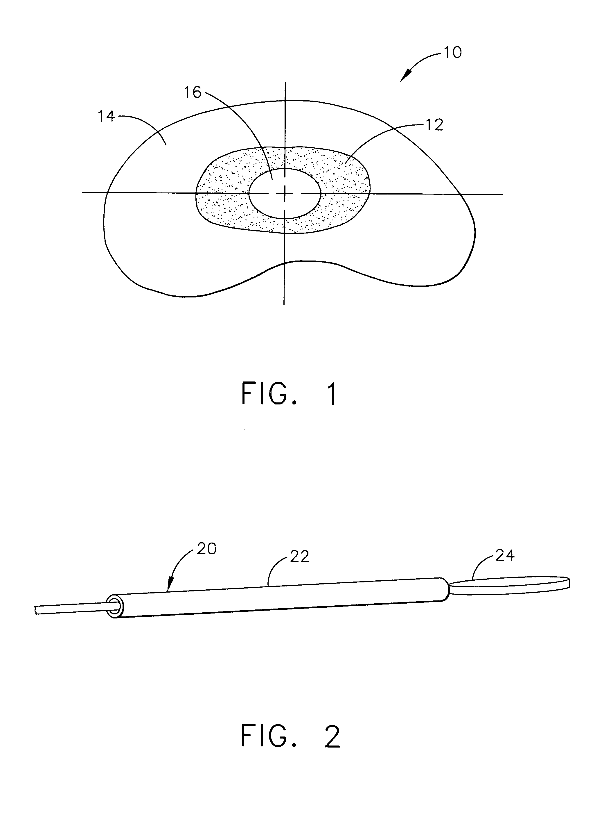
[0055] Referring now to FIG. 1, there is shown a representative spinal disc, generally indicated at 10. Disc 10 contains a nucleus 12 and an annulus 14. Within nucleus 12 is a centrally located cored out section 16. Section 16 is created to precisely locate an artificial nucleus implant which would accept a standard shape. Section 16, which houses the implant, should ideally be centered in the nucleus to accept the natural movement and forces that are generated by normal patient activity.

[0056] To define a standard core section 16 shape, an instrument must be developed which can consistently core out this area within nucleus 12. The instrument should be small in size such that the procedure can be performed as minimally invasive. It is important that the nucleus implant remains centered on the line of force, preventing it from placing undue forces on annulus 14. One method for accomplishing these objectives is to leave annulus 14 in place and some of the tissue of nucleus 12 but to...


PUM


Abstract

A device and method for repairing spinal discs in which the nucleus has been damaged. A central section of the nucleus is cored out using a device which ablates the tissue using RF energy. A nucleus implant comprising a shape memory material is placed in the central section of the disc through a cannula, which implant is activated by body heat to expand and fill the central section, such that the implant emulates the functions and strength of the disc's natural nucleus.

Description

CROSS REFERENCE TO RELATED APPLICATIONS [0001] This application claims benefit from U.S. Provisional Application Ser. No. 60 / 484,091, filed Jul. 1, 2004, which application is incorporated herein by reference.BACKGROUND OF THE INVENTION [0002] 1. Field of the Invention [0003] The present invention relates generally to spinal implants, and, in particular, to devices and methods for repairing discs in which the nucleus has been damaged. [0004] 2. Description of the Prior Art [0005] Due to strain or degenerative disease, the nucleus of a spinal disc often herniates or erupts through the annulus of the disc. This action weakens the disc, as well as creating tremendous pain to the patient as the hernia “bulge” creates pressure on the spinal nerve bundles. [0006] There are currently two common practices that are employed by surgeons to correct this situation: [0007] 1) remove the hernial bulge by nibbling or coring away the tissue which is pressing on the nerve bundles. While this procedur...

Claims


Application Information

Patent Timeline
IPC IPC(8): A61B17/00A61B18/14A61F2/00A61F2/30A61F2/44A61F2/46
CPCA61B18/1492A61F2310/00023A61B2018/00214A61B2018/0022A61B2018/0044A61B2018/00898A61B2218/007A61F2/442A61F2/4611A61F2002/30098A61F2002/30102A61F2002/30579A61F2002/30841A61F2002/4435A61F2002/444A61F2002/4627A61F2210/0033A61F2210/0042A61F2310/00017A61B2017/00261A61F2002/30092
Inventor GRANT, RICHARD L.YOUNG, JOSEPH E.HENDERSON, STEVEN L.
Owner SENTRON MEDICAL
Why Eureka
Try Eureka