

Photo-sensor
- Summary
- Abstract
- Description
- Claims
- Application Information
AI Technical Summary
Benefits of technology
Problems solved by technology
Method used
Image

Examples
first embodiment
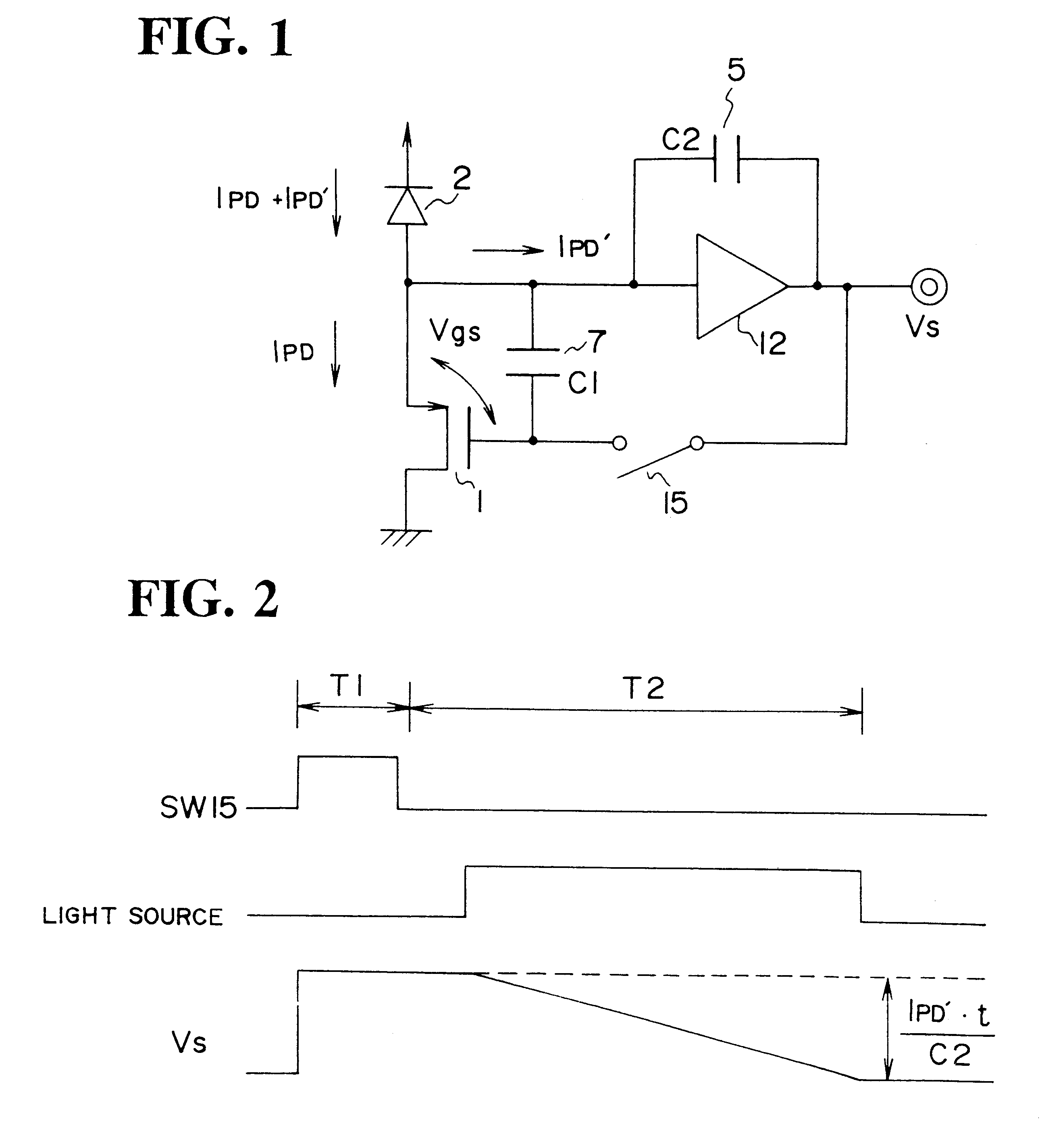
FIG. 1 shows the present invention. This embodiment can be used as, for instance, the light-receiving element 124 of the active AF module as shown in FIG. 10. In the Figure, circuit elements like those in the prior art example described before in connection with FIG. 1 are designated by like reference numerals. As the light source for projecting light on the scene for the distance measurement, an LED or the like is assumed to be used as the light source 120 shown in FIG. 10.
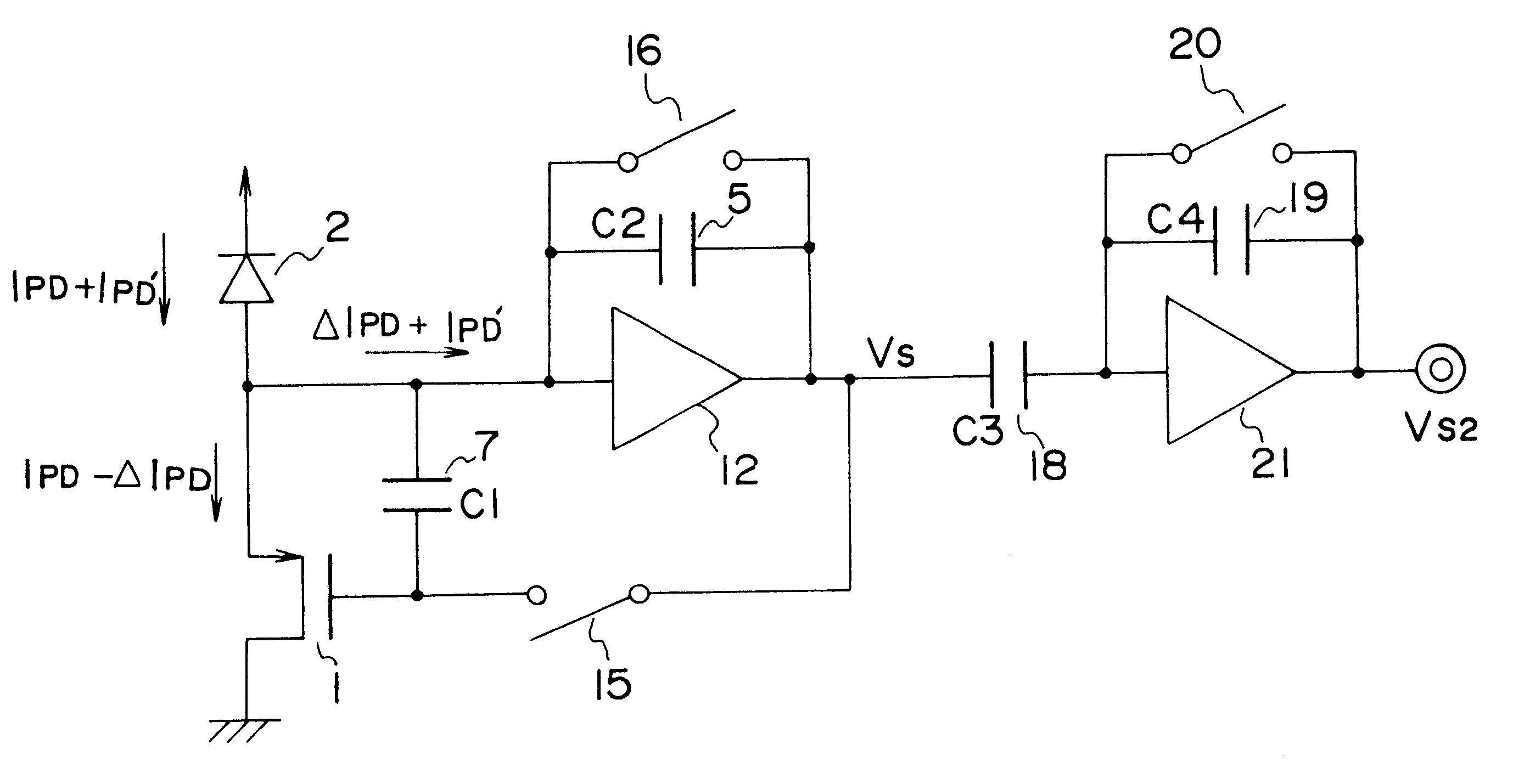
A transistor 1 for detecting signal light has the source connected to one terminal of a photo-diode 2, which has the other terminal connected to a power supply, the drain grounded and the gate connected via a memory switch 15 constituted by a switching transistor or the like to the output of an inverting amplifier 12. A capacitor 7 for storing photo-current is provided between the source and gate of the transistor 1. The connection point between the source of transistor 1 and the photo diode 2 is connected to the...
second embodiment
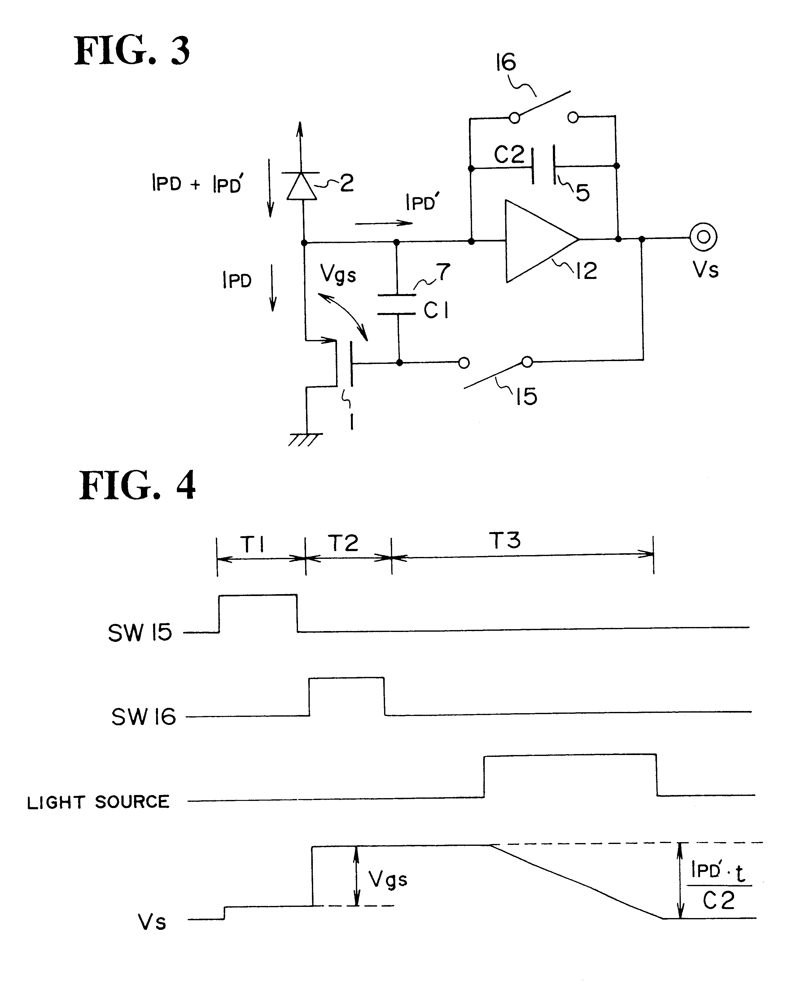
FIG. 3 shows a second embodiment, which is a modification of the structure shown in FIG. 1. In the structure shown in FIG. 1, the output voltage Vs of the inverting amplifier 12 in the period T1 depends on the source-gate voltage V.sub.gs across the transistor 1 and also depends on the photo-current I.sub.PD due to the background light. Therefore, the output voltage Vs of the inverting amplifier 12 in the period T1 is changed in correspondence to the brightness of the background light. Therefore, the reference voltage when detecting the projected light photo-current in the period T2 succeeding the period Td, is changed with changes in the background light.
Accordingly, in FIG. 3 a reset switch 16 is connected in parallel with the projected light detection capacitor 5 to reset the accumulated charge therein. Before the start of integration of projected light photo-current I.sub.PD ', in the period T2 the reset switch 16 is turned on to reset the accumulated charge in the capacitor 5. ...
third embodiment
FIG. 5 shows the present invention. In this embodiment, the feed-back system for the inverting amplifier is realized by using a resistor. Specifically, for detecting the photo-current I.sub.PD ' due to the projected light, a reset switch 16 constituted by a switching transistor or the like and a transimpedance resistor 17 (for photo-current-to-voltage conversion) are connected in series with each other between the input and output sides of the inverting amplifier 12.
FIG. 6 is a time chart showing the operation of the circuit shown in FIG. 5. In the Figure SW15 labels the operation of the memory switch 15, SW16 labels the output of the reset switch 16, LIGHT SOURCE labels the output of the LED as the light source noted before, and Vs labels the output voltage of the inverting amplifier 12 (i.e., the output of the photo-sensor shown in FIG. 5). Referring to the Figure, in the period T1 photo-current I.sub.PD due to the background light is stored in the capacitor 7 by turning on the me...
PUM
 Abstract
Description
Claims
Application Information