Cleaning device
- Summary
- Abstract
- Description
- Claims
- Application Information
AI Technical Summary
Benefits of technology
Problems solved by technology
Method used
Image
Examples
first embodiment
>
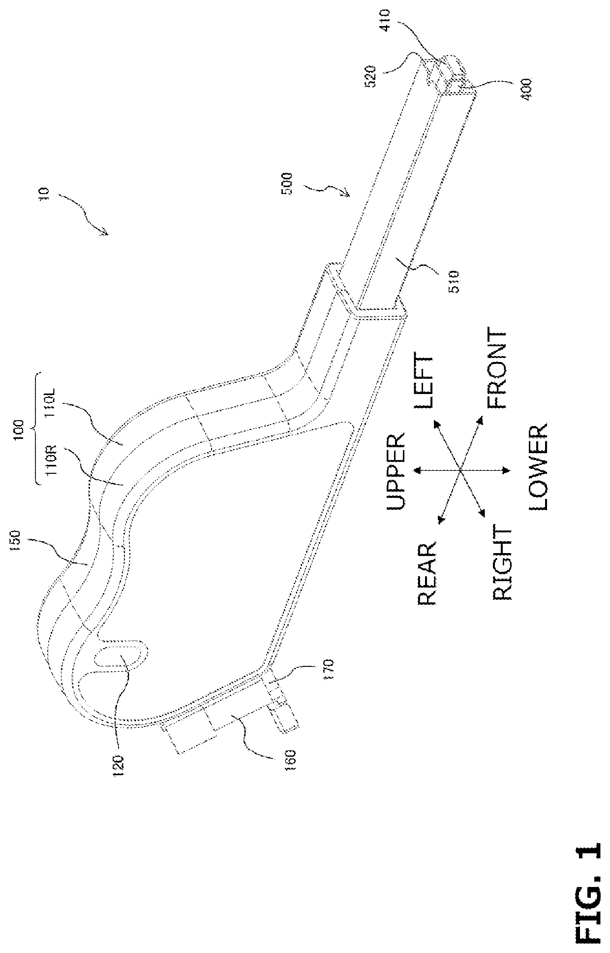
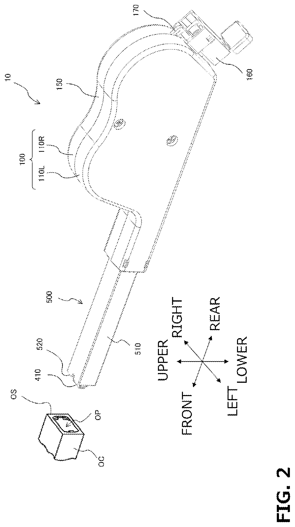
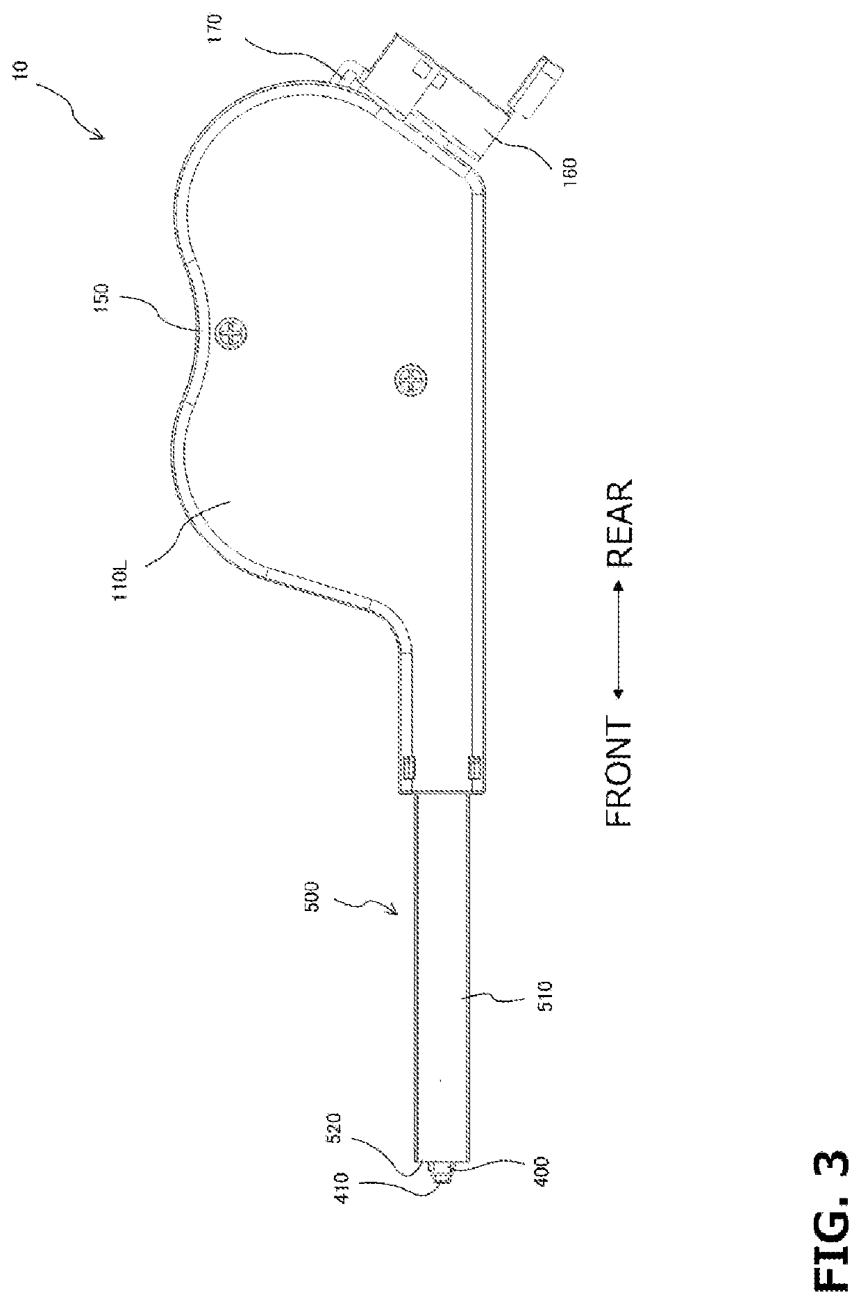
[0121]According to a first execution mode, provided is an optical connector cleaning device (for example, a cleaning device 10 to be described later or the like) including
[0122]a main body (for example, a housing 100 to be described later or the like) housing a supply holder (for example, a supply reel 200 to be described later or the like) to which a cleaning body (for example, a cleaning body CT to be described later, or the like) for cleaning a surface to be cleaned is suppliably held, where the cleaning body has a contaminant collector (for example, a contaminant collector RL to be described later or the like) capable of collecting and holding contaminants,
[0123]a cleaning head (for example, a cleaning head 410 to be described later or the like) on which a cleaning body supplied from the main body is positioned, the cleaning head being held at a constant holding position with respect to the main body,
[0124]a control body (for example, a winding control body 500 to be described ...
second embodiment
[0328]The cleaning device of the second embodiment is a cleaning device of another aspect different from the first embodiment for cleaning the end face from which the guide pins GP protrude. Examples of the object to be cleaned include an optical connector having an end face from which guide pins GP (pin) protrude (MT connector (F12 type multi core optical fiber connector: JIS C 5981), MPO connector (F13 type multi core optical fiber connector: JIS C 5982), MTRJ connector, MPX connector, and the like), and a plug in which 2 to 3 guide pins GP for insertion into a socket of an outlet protrude.
[0329]The cleaning device of the second embodiment includes a contaminant collector that can be punctured with the guide pins GP, and a support body that supports the contaminant collector such that part of the surface of the contaminant collector is exposed (not in contact with the support body). In addition, the thickness of the contaminant collector in a direction normal to the exposed surfac...
example 1
[0397]A mixture of 10 mass % of an ester-based diol having a number average molecular weight of 1500, 80 mass % of an ether-based diol having a number average molecular weight of 2000, and 10% of an ether-based triol having a number average molecular weight of 1500 was prepared as a main agent. A mixture of monomeric diphenylmethane diisocyanate carbodiimide-modified isocyanate, an ether-based triol having a number average molecular weight of 3000, and an ester-based diol having a number average molecular weight of 500 was reacted at 80° C. for 2 hours to obtain a prepolymer having NCO of about 18.9% as a curing agent. The curing agent was transferred to a container, and the main agent was weighed so that the equivalent ratio between the hydroxyl group of the polyol as the main agent and the isocyanate group of the polyisocyanate as the curing agent was 1.2 (equivalent of isocyanate group / equivalent of hydroxyl group), and added dropwise to the curing agent with stirring. After comp...
PUM
 Abstract
Description
Claims
Application Information
 - R&D
- Intellectual Property
- Life Sciences
- Materials
- Tech Scout
- Unparalleled Data Quality
- Higher Quality Content
- 60% Fewer Hallucinations
Browse by: Latest US Patents, China's latest patents, Technical Efficacy Thesaurus, Application Domain, Technology Topic, Popular Technical Reports.
© 2025 PatSnap. All rights reserved.Legal|Privacy policy|Modern Slavery Act Transparency Statement|Sitemap|About US| Contact US: help@patsnap.com


