
Radiation image processing device and radiation image processing method

Pending Publication Date: 2022-03-17
FUJIFILM CORP
View PDF0 Cites 1 Cited by
  • Summary
  • Abstract
  • Description
  • Claims
  • Application Information

AI Technical Summary

Benefits of technology

The invention provides a device and method for processing radiation images to remove scattered radiation components. The device and method estimate the component of the radiation transmitted through a subject and a scattering element using the scattering characteristics of the element. This allows for more accurate removal of scattered radiation components, ultimately resulting in a higher accuracy of the radiation image.

Problems solved by technology

The reason for this is that errors caused by scattered radiation components negatively affect calculation results and it is difficult to obtain accurate calculation results in a case where a calculation using a radiation image is made.

Method used


Image

  • Radiation image processing device and radiation image processing method
  • Radiation image processing device and radiation image processing method
  • Radiation image processing device and radiation image processing method

Examples


first embodiment

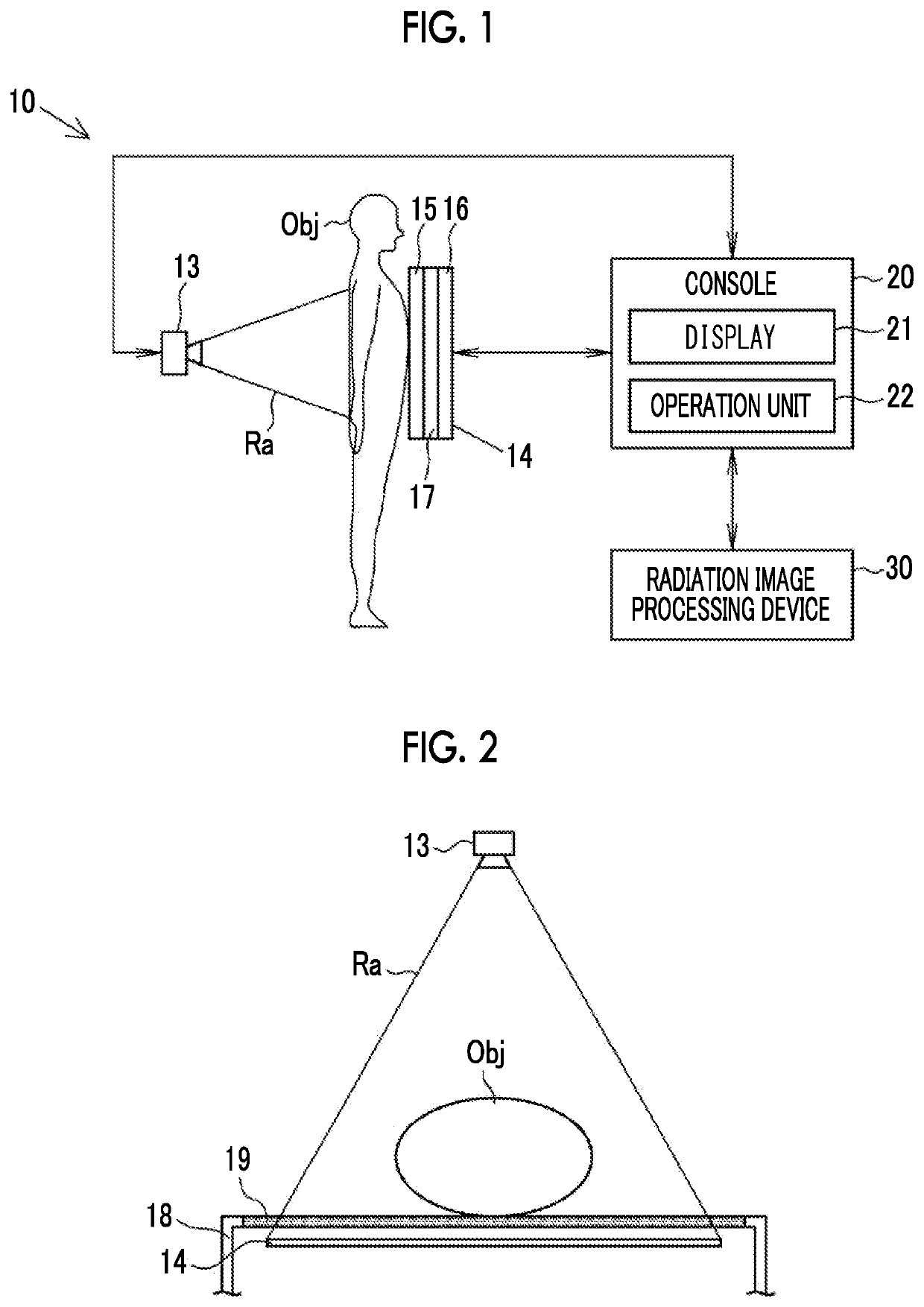
[0042]As shown in FIG. 1, a radiography system 10 comprises a radiation source 13, a radiography panel 14, a console 20, and a radiation image processing device 30.

[0043]The radiography system 10 irradiates a radiography panel 14 with radiation, which is emitted from a radiation source 13, such as an X-ray source, and has been transmitted through a subject Obj, to acquire a radiation image of the subject Obj lying on an imaging table 18 (see FIG. 2). Accordingly, the range of radiation to be applied to the subject Obj is defined. The radiation image is input to the console 20.

[0044]The radiation source 13, the radiography panel 14, and the console 20 form a radiography device. The radiation source 13 is a device generating radiation Ra required for imaging, and consists of a radiation tube that generates the radiation Ra, a high voltage generating circuit that generates a high voltage required to allow the radiation tube to generate the radiation Ra, and the like. The radiation sour...

second embodiment

[0096]In a radiography system of a second embodiment, a radiation image processing device 100 shown in FIG. 12 is used instead of the radiation image processing device 30 according to the first embodiment. The radiation image processing device 100 comprises a radiation image acquisition unit 33, an imaging condition acquisition unit 102, a body thickness derivation unit 103, a characteristic acquisition unit 104, a radiation distribution derivation unit 105, and a second image generation section 106. The radiation image processing device according to the embodiment of the invention may have both the function of the radiation image processing device 30 according to the first embodiment and the function of the radiation image processing device 100 according to the second embodiment.

[0097]In the radiation image processing device 100, programs related to various types of processing are incorporated in a program memory. The programs incorporated in the program memory are executed by a ce...


PUM


Abstract

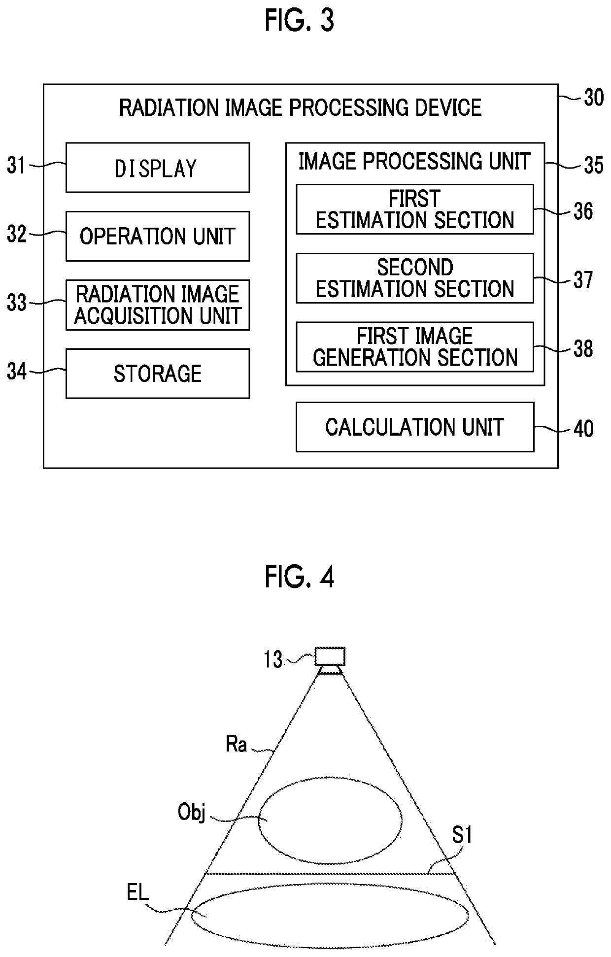
A radiation image processing device includes: a first estimation section that estimates components of radiation Ra having passed through a subject Obj using a first radiation image taken from the subject Obj; a second estimation section that estimates components of the radiation Ra, which have passed through an additional scattering element EL, using an estimation result of the first estimation section and scattering characteristics f2(X) of the additional scattering element EL; and a first image generation section that generates a second radiation image, which has been transmitted through the subject Obj and the additional scattering element EL, using an estimation result of the second estimation section.

Description

CROSS-REFERENCE TO RELATED APPLICATIONS[0001]This application is a Continuation of PCT International Application No. PCT / JP2020 / 020848 filed on 27 May 2020, which claims priority under 35 U.S.C. § 119(a) to Japanese Patent Applications No. 2019-098660 filed on 27 May 2019 and No. 2020-091087 filed on 26 May 2020. The above application is hereby expressly incorporated by reference, in its entirety, into the present application.BACKGROUND OF THE INVENTION1. Field of the Invention[0002]The present invention relates to a radiation image processing device and a radiation image processing method that perform image processing on a radiation image.2. Description of the Related Art[0003]A radiography device imaging a subject using radiation, such as an X-ray, has been spread in the past. For example, in a case where a subject is a human or an animal, radiation images are used for the diagnosis or the like of a lesion.[0004]It is desirable that a radiation image is formed in radiography using...

Claims


Application Information

Patent Timeline
IPC IPC(8): A61B6/00
CPCA61B6/5282A61B6/4291A61B6/4266A61B6/4241A61B6/463A61B6/482A61B6/483A61B6/488A61B6/50A61B6/5205A61B6/5258A61B6/544A61B6/545A61B6/588A61B6/583A61B6/585
Inventor TAKAHASHI, TOMOYUKI
Owner FUJIFILM CORP
Learn More