Composite calibration method of mold surface optical measurement system

A technology of optical measurement system and calibration method, which is applied in the field of camera calibration, projector calibration and system geometric parameter calibration, and surface optical measurement system comprehensive calibration, which can solve the problem of unfavorable projector and system parameter calibration, affecting the accuracy of basic data acquisition and Efficiency, unsuitability and other issues

Inactive Publication Date: 2005-01-26
SHANGHAI JIAO TONG UNIV
View PDF0 Cites 45 Cited by
  • Summary
  • Abstract
  • Description
  • Claims
  • Application Information

AI Technical Summary

Problems solved by technology

In the prior art, Jean-YvesBouguet proposed in Http: / / www.vision.caltech.edu / bouguetj / index.html a semi-automatic method of human interaction to obtain calibration basic data, which is easy to operate, but human factors obviously affect The accuracy and efficiency of basic data acquisition, and it is not conducive to the calibration of projectors and system parameters
Andrew Certain and Li Zhang use the red pattern calibration plate to calibrate the camera in the article Hierarchical Stripe Scanning in http: / / www.cs.washington.edu / homes / lizhang / projects / hstripe, and then project the blue pattern onto the calibration plate, Recorded by a color camera, the projector is calibrated by filtering out the red pattern and retaining the blue pattern, which is obviously not suitable for the calibration of black and white cameras and physical raster projectors commonly used in 3D measurement systems

Method used


Image

  • Composite calibration method of mold surface optical measurement system
  • Composite calibration method of mold surface optical measurement system
  • Composite calibration method of mold surface optical measurement system

Examples


Embodiment Construction

[0015] The specific implementation of the present invention will be further described below in conjunction with the accompanying drawings.

[0016] Such as figure 1 , figure 2 , image 3 As shown, according to the comprehensive calibration method of the profile optical measurement system of the present invention, the specific implementation steps of comprehensive calibration of a structured light projection three-dimensional profile measurement system are as follows:

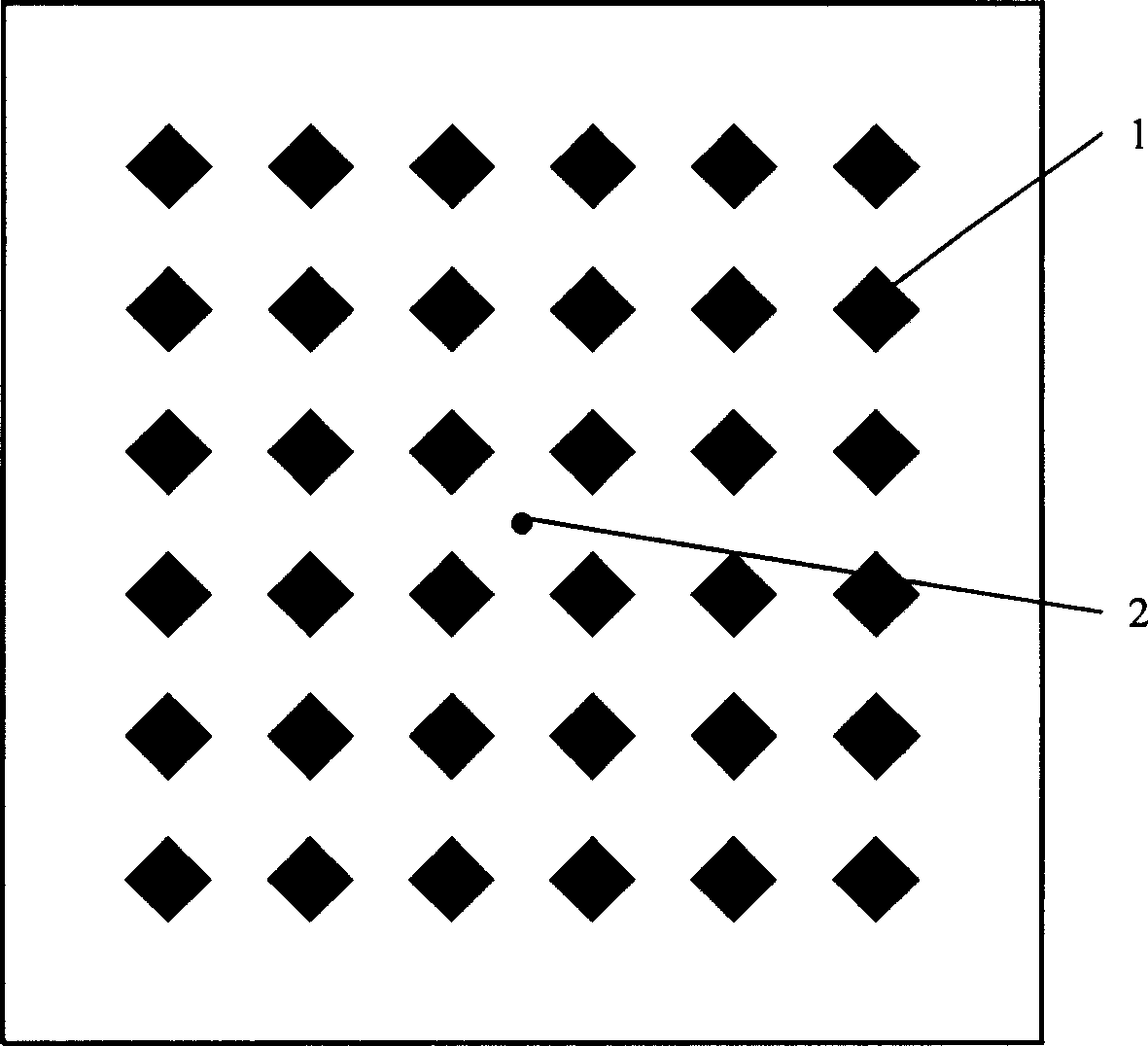
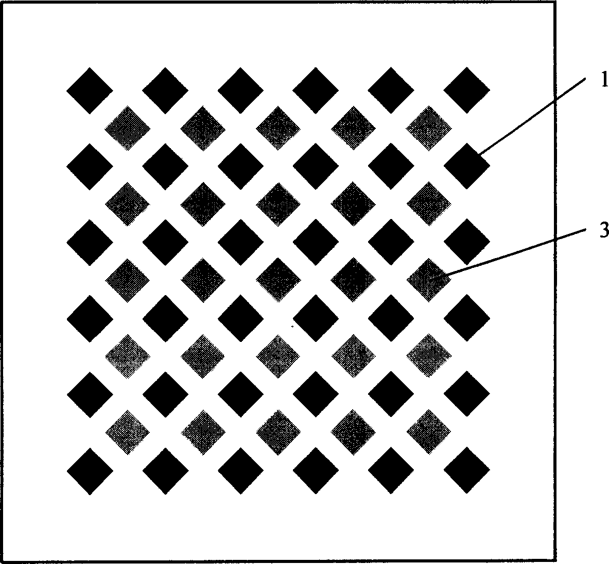
[0017] 1. Make calibration board and projector calibration grating: according to figure 1 According to the characteristics of the measurement system itself, a plane calibration board of corresponding size is made, with white as the background color, and a uniformly distributed black diamond-shaped square grid array 1 on it, and a black positioning point 2 marked in the center of the calibration board. The pattern of the calibration grating of the projector adopts the same diamond-shaped grid array, and its s...


PUM


Abstract

It is the general calibration method of model-surface optical measuring system. Calibration board on which is located evenly with black rhombic square array in the white background and projector calibration grating of corresponding rhombic square array are uniquely employed in this invention. The calibration board position is corrected by laser to make the projector to project rhombic square array into the white interstice on the calibration board whose images before and after shutting up the projector is recorded by the camera used as calibration image. Then the basic data are obtained through the processing of the calibration image and accordingly the space coordinates of the projector calibration dots can be calculated. The calibration of the projector is realized on the basic datum through matching the coordinates of corresponding calibration dots of projector image. According to the relationship between the coordinate systems of projector and camera the calibration of systematic geometric parameter can be realized. The invention is of great engineering utility and can solve the accuracy problem of automatic extraction and realize the integrated calibration of camera and projector.

Description

Technical field: [0001] The invention relates to a comprehensive calibration method for a profile optical measurement system, in particular to a method for camera calibration, projector calibration and system geometric parameter calibration of a structured light projection three-dimensional profile measurement system, which belongs to mechanical engineering and optical measurement technology field. Background technique: [0002] The structured light projection three-dimensional surface measurement system is based on the principle of triangulation, and is composed of a camera and a projector. The optical models of the camera and projector are both pinhole models. Geometric parameters such as the center distance d, the distance L from the optical center to the reference plane, and the field of view width FW of the projector or camera on the reference plane all affect the measurement results. Therefore, the internal and external parameters of the camera and projector based on t...

Claims


Application Information

Patent Timeline
Patent Type & Authority Applications(China)
IPC IPC(8): G01B11/00G01B11/03G01B11/24
Inventor 严隽琪习俊通姜涛
Owner SHANGHAI JIAO TONG UNIV
Why Eureka
Try Eureka