Layered fertilizer applying device

A technology of layered fertilization and height detection device, applied in fertilization devices, fertilizer distributors, planting methods, etc., can solve the problems of affecting growth and development, seeds cannot absorb enough nutrients, and uneven distribution of nutrients, so as to ensure the depth of fertilization, improve the Fertilization effect, effect of enhancing absorption effect

Pending Publication Date: 2018-06-19
QINGDAO AGRI UNIV
0 Cites 15 Cited by

AI-Extracted Technical Summary

Problems solved by technology

[0003] However, the existing automatic fertilization devices usually can only achieve single-layer fertilization, that is, the fertilizer is piled at a single depth and position in the soil
This method of fertilization will lead to uneven distribution of nutrients in the soil, and the seeds may not be able to absorb enough nutrients due to deviation from the area where the fertilizer is located, affe...

Method used

Because the front end of the fertilizer discharge box is narrow and the rear end is wide, the front end and the rear end are connected by an inclined plane, so when the fertilizer discharge box moves forward in the soil, the resistance from the soil received can be greatly reduced ;Because the fertilizer discharge box adopts the way of opening on the rear side to discharge fertilizer, it can effectively prevent the soil from blocking the fertilizer discharge port and improve the fertilization effect.
Layered fertilization device of the present invention can carry out layered, multi-dimensional fertilization to soil, to strengthen the absorption effect of seed to fertilizer, be beneficial to the processes such as seed subsequent germination, seedling; Layered, multi-dimensional fertilization mode It can improve the utilization rate of fertilizer, not only reduce the waste of fertilizer, but also be more environmentally friendly, and can alleviate or avoid compaction of soil.
Layered fertilization device of the present invention, by arranging detection and adjusting device, the fertilization depth of layered fertilization device can be regulated voluntarily according to the change of ground height, thus guarantees the uniformity and stability of fertilization depth, is conducive to improving fertilization...

Abstract

The invention discloses a layered fertilizer applying device. The layered fertilizer applying device comprises a first fertilizer applying assembly and a second fertilizer applying assembly, wherein afertilizer inlet of the first fertilizer applying assembly and a fertilizer inlet of the second fertilizer applying assembly are communicated with a fertilizer box; and a fertilizer outlet of the second fertilizer applying assembly is positioned above the fertilizer outlet of the first fertilizer applying assembly. The layered fertilizer applying device can perform layered multi-dimensional fertilizer application on soil to improve absorption effect, on fertilizers, of seeds, so that follow-up processes such as budding, seedling grow-up of the seeds are facilitated; the layered and multi-dimensional fertilizer applying mode can improve a fertilizer utilization rate, can reduce waste of fertilizers, is more environmentally friendly, and can relieve or avoid soil hardening; and detecting and regulating devices are arranged, so that fertilizer applying depth of the layered fertilizer applying device can be automatically regulated according to ground height changes, and therefore, unification and stability of fertilizer applying depth are guaranteed, and the fertilizer applying effect is improved in a facilitated mode.

Application Domain

PlantingFertiliser distributers +1

Technology Topic

FertilizerAbsorption effect +4

Image

  • Layered fertilizer applying device
  • Layered fertilizer applying device
  • Layered fertilizer applying device

Examples

  • Experimental program(1)

Example Embodiment

[0023] In order to better understand the purpose, function and specific design scheme of the present invention, the layered fertilization device of the present invention will be described in further detail below.
[0024] The layered fertilization device of the present invention is mainly applied to planting machinery and equipment, and its main function is to cooperate with the planting process to fertilize the sown land to ensure that the seeds of the crops can absorb enough nutrients during the germination and seedling stages.
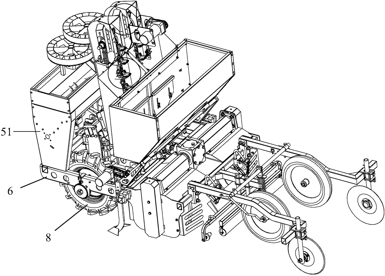
[0025] Such as figure 1 As shown, taking a potato planter as an example, the potato planter includes a rack beam 6 which is suspended on a tractor or traction equipment, and ground wheels 8 are symmetrically arranged on both sides of the rack beam 6. The tractor or traction equipment drags the rack beam 6 to move the potato planter forward. The fertilizer box 51 is arranged on the frame beam 6, and the layered fertilization device is arranged below the fertilizer box 51.
[0026] Such as figure 2 As shown, the layered fertilization device is fixedly connected to the frame cross beam 6 by U-shaped bolts 53. Such as image 3 with Figure 4 As shown, the layered fertilization device includes a lower fertilizer discharge pipe 521. The lower fertilizer discharge pipe 521 is a vertically arranged hollow pipe body. The upper end opening is connected to the fertilizer box 51, and the lower fertilizer outlet 531 at the lower end extends into the soil to be fertilized. in. The fertilizer in the fertilizer tank 51 flows into the lower fertilizer discharge pipe 521, and is discharged into the soil through the lower fertilizer outlet 531. The lower fertilizer outlet 531 is used to fertilize the soil in the deep layer.
[0027] Preferably, the lower fertilizer outlet 531 includes an oblique notch 533 connected to the bottom end of the lower fertilizer outlet 531 and has a triangular shape. The bottom end of the chute 533 has a sharp corner, and the front side of the sharp corner is a backward slope structure. The sharp corner is conducive to the lower fertilizer outlet 531 to extend into the ground and cut the soil. The slope can reduce the downward output. The resistance of the mouth 531 to move forward in the soil. The rear side of the sharp corner, that is, the bottom side of the triangle facing the rear side is an open structure, the open structure is arranged in a vertical direction, and is perpendicular to the ground; after the fertilizer flows to the lower fertilizer outlet 531, it is discharged into the soil through the open structure. The opening structure facing the rear side and arranged in the vertical direction receives less resistance from the soil when it moves, which is more conducive to the discharge of fertilizer.
[0028] A ditching shovel 56 is fixedly arranged on the front side of the lower fertilizer outlet 531, and the ditching shovel 56 is fixedly connected to the pipe body of the lower fertilizer pipe 521. The ditching shovel 56 is a shovel-like structure inclined to the front. When fertilizing, the ditching shovel 56 extends into the soil, and the planter moves forward to drive the ditching shovel 56 to move forward to shovel a row on the ground. In the fertilizer ditch, the lower fertilizer outlet 531 located on the rear side of the ditching shovel 56 can discharge fertilizer into the fertilizer discharge ditch.
[0029] An upper fertilization component is provided on the rear side of the lower fertilizer discharge pipe 521, and the upper fertilization component is used to fertilize a shallow layer of soil, and the upper fertilization component can automatically adjust the fertilization depth according to the change of the ground surface.
[0030] Specifically, the upper fertilizer application assembly includes an upper fertilizer discharge pipe 522, which is a vertically arranged hollow tubular structure, the upper end of which is in communication with the fertilizer box 51, and the lower end is connected with an upper fertilizer outlet 532. The fertilizer in the fertilizer tank 51 flows to the upper fertilizer outlet 532 through the upper fertilizer discharge pipe 522, and is discharged into the soil through the upper fertilizer outlet 532. The height of the upper fertilizer outlet 532 is higher than the lower fertilizer outlet 531.
[0031] One side of the upper fertilizer discharge pipe 522 is fixedly connected with a vertically arranged hydraulic rod 58, and the fixed end of the hydraulic rod 58 is fixedly connected with the rod body of the lower fertilizer discharge pipe 521. A hydraulic valve 55 is arranged above the hydraulic rod 58 and the hydraulic valve 55 can control the hydraulic rod 58 to move up and down in a vertical direction. The upper fertilizer pipe 522 can move up and down in the vertical direction under the drive of the hydraulic rod 58.
[0032] A photoelectric sensor 57 is also arranged at the position where the hydraulic rod 58 is fixedly connected to the lower fertilizer pipe 521, and the photoelectric sensor 57 can detect the ground height in real time. A control system is also connected to the hydraulic valve 55. The control system can receive the signal detected by the photoelectric sensor 57 and control the up and down movement of the hydraulic rod 58 according to the content of the signal. By adjusting the movement distance of the hydraulic rod 58, the upper fertilizer outlet 532 is controlled to enter the soil. In the depth.
[0033] In addition, a fertilizer discharging device is provided between the fertilizer box 51 and the lower fertilizer discharging pipe 521 and the upper fertilizer discharging tube 522. One end of the fertilizer discharging device is connected to the fertilizer tank 51, and the other end is connected to the lower fertilizer discharging pipe 521 and the upper fertilizer discharging pipe. The upper end of the tube 522 is connected. The fertilizer discharging device is driven by a motor or other power device, and under the control of the control system, the fertilizer in the fertilizer tank 51 is quantitatively discharged into the lower fertilizer discharge pipe 521 and the upper fertilizer discharge pipe 522.
[0034] Of course, the lower fertilizer discharge pipe 521 and the upper fertilizer discharge pipe 522 can be connected to the fertilizer applicator through separate pipes in the manner described above; the lower fertilizer discharge pipe 521 and the upper fertilizer discharge pipe 522 can also be connected to the fertilizer applicator. The lower end merges to form a pipe, and then connects with the fertilizer applicator.
[0035] The working process of the upper fertilization component will be described in detail below in conjunction with the above description.
[0036] First, calculate a reasonable ground height value according to the fixed fertilization depth, and input the ground height value into the control system of the upper fertilization component for preset. During the fertilization process, the photoelectric sensor 57 always detects the ground height.
[0037] When the layered fertilizer applicator moves forward with the planter, the height of the ground detected by the photoelectric sensor 57 also changes in real time due to uneven ground.
[0038] When the ground height detected by the photoelectric sensor 57 is the preset height value, the control system controls the hydraulic valve 55 to keep the telescopic length of the hydraulic rod 58 unchanged;
[0039] When the ground height detected by the photoelectric sensor 57 is higher than the preset height, the control system controls the hydraulic valve 55 to extend the hydraulic rod 58 downward by the corresponding difference to ensure that the fertilization depth of the upper fertilizer outlet 532 is not affected by the ground. Rise in height;
[0040] When the ground height detected by the photoelectric sensor 57 is lower than the preset height value, the control system controls the hydraulic valve 55 to shorten the hydraulic lever 58 upward by the corresponding difference to ensure that the fertilization depth of the upper fertilizer outlet 532 is not affected by the ground height The decline and decline.
[0041] Through the above working methods, the upper fertilization component can adjust the fertilization depth in real time according to the change of the ground surface height to ensure the uniformity of the fertilization depth and improve the fertilization effect.
[0042] Further, such as image 3 As shown, a fertilizer discharge box is connected to the upper fertilizer outlet 532. Such as Figure 5 with Image 6 The specific structural diagram of the fertilizer discharging box is shown. The fertilizer discharging box includes a trapezoidal box body 539. The end of the box body 539 facing the front side is narrow and closed; the end of the box body 539 facing the rear side It is wide and open. An opening 535 is provided on the top surface of the fertilizer box. The opening 535 is fixedly connected to the bottom end of the upper fertilizer tube 522. The fertilizer flows into the fertilizer box through the upper fertilizer tube 522, and then is discharged from the open end of the fertilizer box. Into the soil.
[0043] Because the front end of the fertilizer box is narrow and the rear end is wider, the front end and the rear end are connected by an inclined plane, so when the fertilizer box moves forward in the soil, the resistance from the soil can be greatly reduced; The fertilizer box uses the opening on the rear side to discharge fertilizer, so it can effectively prevent soil from clogging the fertilizer discharge opening and improve the fertilization effect.
[0044] Further, such as Figure 5 As shown, in the inside of the fertilizer box, a left partition 533 and a right partition 534 are arranged in a vertical direction, and both the left partition 533 and the right partition 534 are thin plate parts. One end of the left partition 533 is fixedly connected below the opening 535, and the other end is inclined to the left side of the box body 539 along the left side plate of the box body 539; one end of the right partition 534 is fixedly connected below the opening 535, and the other end One end is inclined to the right side of the box body 539 along the right side plate of the box body 539. The bottom edges of the left partition 533 and the right partition 534 are both fixedly connected to the bottom plate of the box body 539.
[0045] The left partition 533 and the right partition 534 can divert and guide the fertilizer flowing into the fertilizer box. After the fertilizer flows into the fertilizer box through the upper fertilizer tube 522, due to the blocking of the left partition 533 and the right partition 534, the fertilizer cannot be directly discharged into the soil through the open end of the rear side of the fertilizer box, and the fertilizer can only be discharged along the left partition The inclined directions of the 533 and the right partition 534 are respectively discharged from the left and right sides of the open end of the rear side of the fertilizer discharging box. Through the above structure, the fertilizer discharging box can achieve the effect of uniformly fertilizing in the left and right directions simultaneously.
[0046] Based on the above description, the lower fertilizer outlet 531 and the upper fertilizer outlet 532 are fertilized together to form a triangular three-dimensional fertilization structure. That is, the lower fertilizer outlet 531 applies fertilizer in the deep soil, and the upper fertilizer outlet 532 applies fertilizer on the left and right sides above the lower fertilizer outlet 531, so that the position of the fertilizer in the soil forms a triangle. The seeds are sown in the center of the triangular three-dimensional fertilization structure, which can enhance the fertilizer absorption effect of the seeds, improve the fertilizer utilization rate, and alleviate the problem of soil compaction caused by residual fertilizer.
[0047] Such as Image 6 As shown, the open end of the rear side of the fertilizer box can be provided with a cover plate 537. The cover plate 537 is an inclined trapezoidal plate structure and is detachably connected to the rear end of the fertilizer discharging box. The lower end of the cover plate 537 and the lower end of the box body 539 have openings through which fertilizer can be discharged out of the fertilizer discharging box. The cover 537 can block the soil from entering the inside of the fertilizer discharging box, and further prevent the soil from clogging the upper fertilizer outlet 532.
[0048] A reinforcing plate 536 can be arranged between the left partition 533 and the right partition 534 to enhance the strength of the fertilizer box and avoid deformation of the fertilizer box due to soil compression and affect the fertilization effect.
[0049] Further, such as image 3 with Figure 4 As shown, a retaining plate 54 is connected to the lower fertilizer discharge pipe 521. The retaining plate 54 has a V-shaped plate structure and is vertically arranged on both sides of the upper fertilizer outlet 532. The front end of the retaining plate 54 is connected to the front side of the rod body of the lower fertilizer discharge pipe 521, and the V-shaped opening at the other end extends to both sides of the upper fertilizer outlet 532. The retaining plate 54 can block the soil on both sides of the upper fertilizer outlet 532 from entering the fertilizer discharging box, so as to prevent the fertilizer discharging box from being blocked.
[0050] A positioning plate 59 is fixed on the front side of the lower fertilizer pipe 521. The positioning plate 59 is provided with a plurality of positioning holes, which are evenly arranged in the vertical direction; the front end of the retaining plate 54 is provided with a plurality of small holes, A plurality of small holes are evenly arranged along the vertical direction. The bolts pass through the small holes on the front end of the retaining plate 54 and the positioning holes on the positioning plate, and the retaining plate 54 can be fixedly connected to the lower fertilizer pipe 521. By adjusting the positions of the positioning holes on the positioning plate 59 and the small holes on the retaining plate 54, the installation height of the retaining plate 54 can be adjusted so that the height of the retaining plate 54 matches the height of the upper fertilizer outlet 532.
[0051] The layered fertilization device of the present invention can perform layered and multi-dimensional fertilization on the soil to enhance the absorption effect of the seed on the fertilizer, which is beneficial to the subsequent germination and seedling process of the seed; the layered, multi-dimensional fertilization method can improve the fertilizer The utilization rate can not only reduce the waste of fertilizer, but also be more environmentally friendly, and can alleviate or avoid soil compaction.
[0052] The layered fertilization device of the present invention is equipped with detection and adjustment devices, so that the fertilization depth of the layered fertilization device can be adjusted automatically according to the change of the ground height, thereby ensuring the uniformity and stability of the fertilization depth, and is beneficial to improving the fertilization effect.
[0053] The present invention has been further described above with the help of specific embodiments, but it should be understood that the specific description here should not be construed as limiting the essence and scope of the present invention. Those of ordinary skill in the art will comment on the above after reading this specification. Various modifications made to the embodiments fall within the protection scope of the present invention.

PUM

no PUM

Description & Claims & Application Information

We can also present the details of the Description, Claims and Application information to help users get a comprehensive understanding of the technical details of the patent, such as background art, summary of invention, brief description of drawings, description of embodiments, and other original content. On the other hand, users can also determine the specific scope of protection of the technology through the list of claims; as well as understand the changes in the life cycle of the technology with the presentation of the patent timeline. Login to view more.

Similar technology patents

Multi-activity food containing collagen peptide and preparation method of multi-activity food

PendingCN114271503AImprove absorptionGood water solubility
Owner:兆鑫堂(山东)生物科技有限公司

Composite neutron absorbing material and preparation method thereof

PendingCN114464333AImprove absorptionImprove high temperature resistance and mechanical strength
Owner:镇江华核装备有限公司

Irradiation of ispaghula

InactiveUS7288225B2improve absorption
Owner:RECKITT BENCKISER HEALTHCARE (UK) LTD

Titanium nanosheet/graphene-based traditional Chinese medicine hot compress device

InactiveCN112007267Apromote blood circulationImprove absorption
Owner:北京康烯科技创新研究有限公司

Novel intelligent unmanned harvester utilizing solar energy

PendingCN114246065AImprove absorptiongood working condition
Owner:NANTONG EOPPLY NEW ENERGY ELECTRIC CO LTD

Classification and recommendation of technical efficacy words

  • increase profit
  • Improve absorption

Hydrodewaxing method for diesel fraction

ActiveCN102453531ARaise the reaction temperatureincrease profit
Owner:CHINA PETROLEUM & CHEM CORP +1

Full-period electric pressure cooker production control method

InactiveCN107713732ATargetedincrease profit
Owner:GUANGDONG HUILIPU ROAD & BRIDGE INFORMATION ENG

Mobile phone

InactiveCN102938796Aincrease profit
Owner:ZTE CORP

Window display method and system of application program and mobile terminal

ActiveCN102999253Aincrease profit
Owner:BEIJING QIYI CENTURY SCI & TECH CO LTD

Heating and dispenser system

InactiveUS20110200381A1improve absorption
Owner:ACCESS BUSINESS GRP INT LLC

Convenient okra tender fruit dry powder, dried flower powder and seed powder food and production method thereof

InactiveCN104207051ABalanced nutritionImprove absorption
Owner:JIASHAN BALINGYI AGRI BIOLOGICAL SCI & TECH

Glp-1 derivatives and transmicosal absorption preparations thereof

InactiveUS20060194720A1high absorptionimprove absorption
Owner:SANWAKAGUKU KENKYUSHO CO LTD

Battery automatic electrolyte injection equipment

PendingCN106654147AImprove absorptionReduce use cost
Owner:SHENZHEN HEROSUN AUTOMATION CO LTD

Deep-ditch fertilizing device of landscape garden

InactiveCN108184400AImprove absorptionSimplify the fertilization process
Owner:ZHENGZHOU GUOZHI NETWORK TECH CO LTD
Why Eureka
Try Eureka