Image forming apparatus
a technology of forming apparatus and forming tube, which is applied in the direction of electrographic process apparatus, instruments, computing, etc., can solve the problems of gradual decrease of the amount of remaining consumable material, and the like, which are necessary for printing in normal printing of other users, and achieve the effect of preventing the lack of consumable material during printing
- Summary
- Abstract
- Description
- Claims
- Application Information
AI Technical Summary
Benefits of technology
Problems solved by technology
Method used
Image
Examples
first embodiment
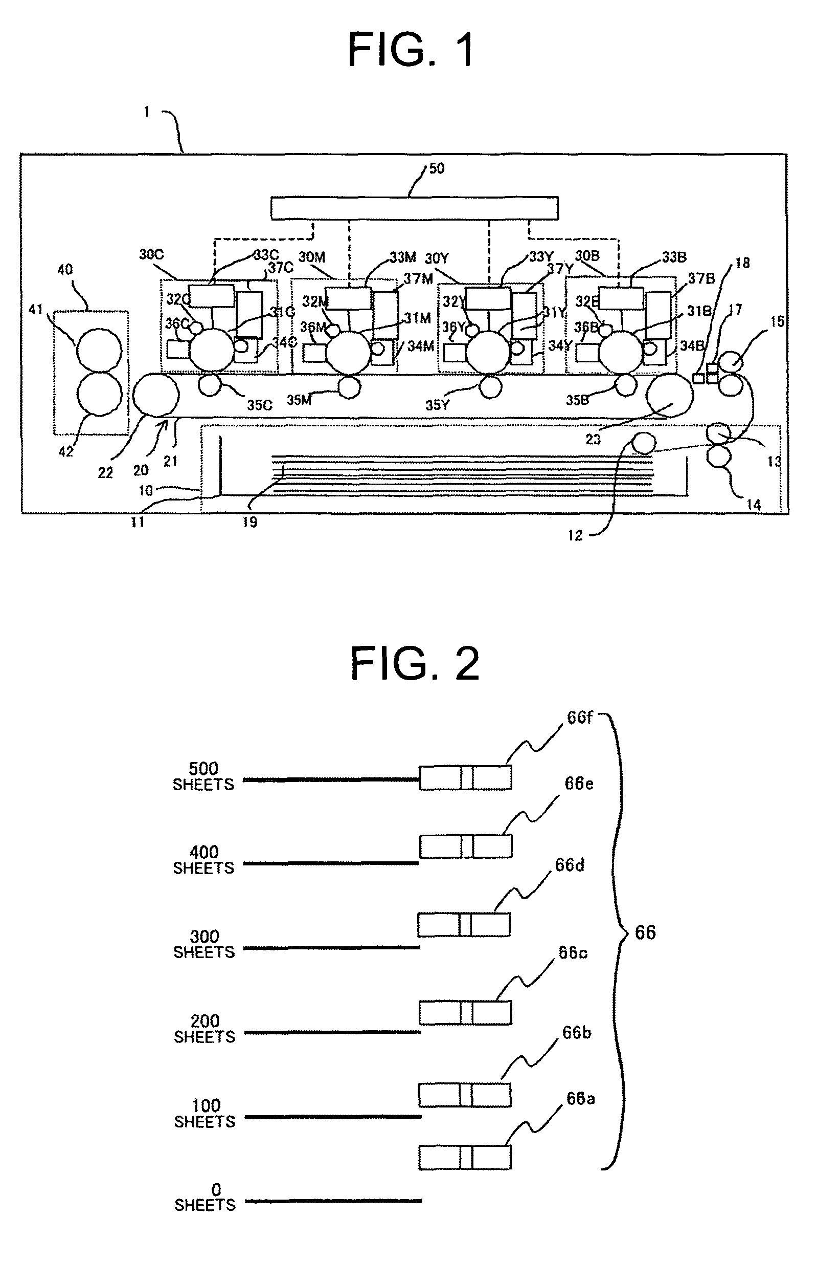
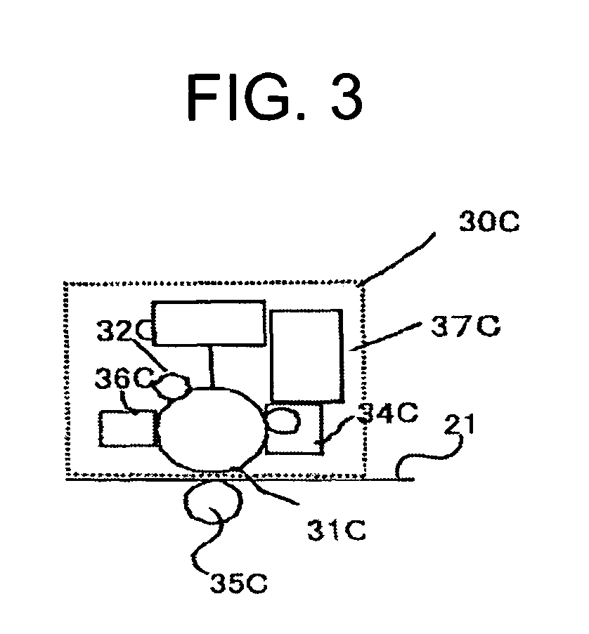
[0033]FIG. 1 is a diagram showing one example of the structure of the image forming apparatus described in the first embodiment. The image forming apparatus described in the first embodiment contains a paper supply unit 10, a feed belt mechanism 20, an image forming unit 30, a fusion unit 40, and a control unit 50.
[0034]The paper supply unit 10 is formed of the print tray 11, a pickup roller 12, a feed roller 13, a retard roller 14, a registration roller pair 15, a paper thickness detection unit 17, and an edge sensor 18.
[0035]The print tray 11 can store any size of recording paper 19 serving as the medium on which the image is formed. For example, the print tray 11 can hold 550 sheets of the recording paper 19. The print tray 11 is a box-shaped unit having at least an opening on top for removing the recording paper 19 serving as the medium. A scale is formed on the side of the print tray 11 having, for example, marks for every 100 sheets of paper. The print tray 11 is equipped with...
second embodiment
[0122]The image forming apparatus described in the second embodiment, as shown in FIG. 14, is an image forming apparatus in which the control unit 50 described in the first embodiment is further equipped with a consumable material usage amount detection unit 66 that detects the amount of consumable material to be used for the newly received printing data. The other units of the image forming apparatus of the second embodiment are the same as those of the first embodiment and therefore the same numbers will be used and explanations will be omitted.
[0123]The consumable material usage amount detection unit 66 detects the amount of consumable material to be used to form the image based on the printing data included in the print job without a designated time sent from the terminal apparatus to execute normal printing. The print job received via the interface unit 56 is analyzed under the control of the CPU 51 and the amount of consumable material to be used is detected from the analyzed ...
third embodiment
[0144]The image forming apparatus described in the third embodiment is an image forming apparatus having a similar structure to the image forming apparatus of the second embodiment. Units that are the same as those of the second embodiment will be given the same number and an explanation will be omitted.
[0145]The image forming apparatus of the third embodiment receives from the terminal apparatus only the printing information included in the newly received print job of normal printing when reserved printing is designated. The consumable material usage amount detection unit 66 detects from the printing information the amount of recording paper 19 serving as the consumable material to be used in the normal printing.
[0146]The consumable material comparison unit 65 receives the information concerning the amount of recording paper 19 needed for the normal printing from the consumable material usage amount detection unit 66. The consumable material comparison unit 65 then compares the rem...
PUM
 Abstract
Description
Claims
Application Information
 - R&D
- Intellectual Property
- Life Sciences
- Materials
- Tech Scout
- Unparalleled Data Quality
- Higher Quality Content
- 60% Fewer Hallucinations
Browse by: Latest US Patents, China's latest patents, Technical Efficacy Thesaurus, Application Domain, Technology Topic, Popular Technical Reports.
© 2025 PatSnap. All rights reserved.Legal|Privacy policy|Modern Slavery Act Transparency Statement|Sitemap|About US| Contact US: help@patsnap.com


