Check patentability & draft patents in minutes with Patsnap Eureka AI!

Laser welding process

a laser welding and process technology, applied in the direction of laser beam welding apparatus, valve details, pipe elements, etc., can solve the problems of affecting the welding effect, and preventing the deposition of sufficient energy, so as to improve the welding

Active Publication Date: 2010-12-28
DANFOSS AS
View PDF13 Cites 6 Cited by
  • Summary
  • Abstract
  • Description
  • Claims
  • Application Information

AI Technical Summary

Benefits of technology

[0007]Due to the size of the focus point, the light may at one time be caught by the gap in which a first part of the light is reflected back and fourth between the edges, and a second part of the light may heat a transition zone between the edges and an outer surface of the component whereby the welding speed can be increased.
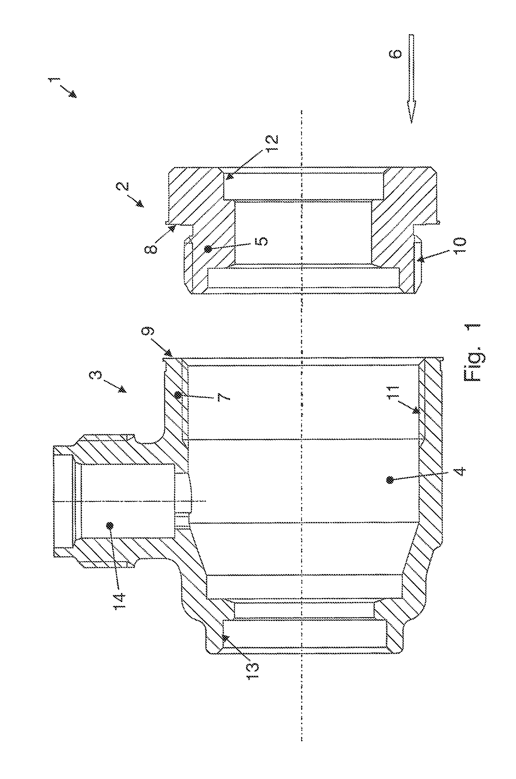
[0009]The first part could be formed with one or more axial protrusions extending in a longitudinal direction from the first one of the axial edges. The axial protrusion could form a cylindrical extension with a diameter which is smaller than the remaining portion of the first part, or it could comprise several oblong elements protruding axially from the first edge. The axial protrusions are from now referred to as a neck of the first part. The neck could be received in a complementary opening, recess or hollowing out which in the following is referred to as a socket, in the second part. The socket may extend from the second edge and in the longitudinal direction into the second part. When the parts are joined via the neck and socket, the first and second edges which are to be welded should be located adjacently at a distance thereby forming the gap. Due to the forming of the neck and socket, the distance between the parts, and thereby the size of the gap can be adjusted in a simple and reliable manner by moving the neck back and forth in the socket in the longitudinal direction. When the gap is adjusted, the parts can remain in this position relative to each other while they are welded by projection of a laser beam in a light beam direction from a laser source and at least partly into the gap without the use of external fixation means. As a result, the quality and the speed of the welding process can be increased. As a further improvement, the neck which is inserted into the socket may form backing for the welding and thus prevent that the molten material flows through the welding joint and into an inner space or conduit of the tubular components.
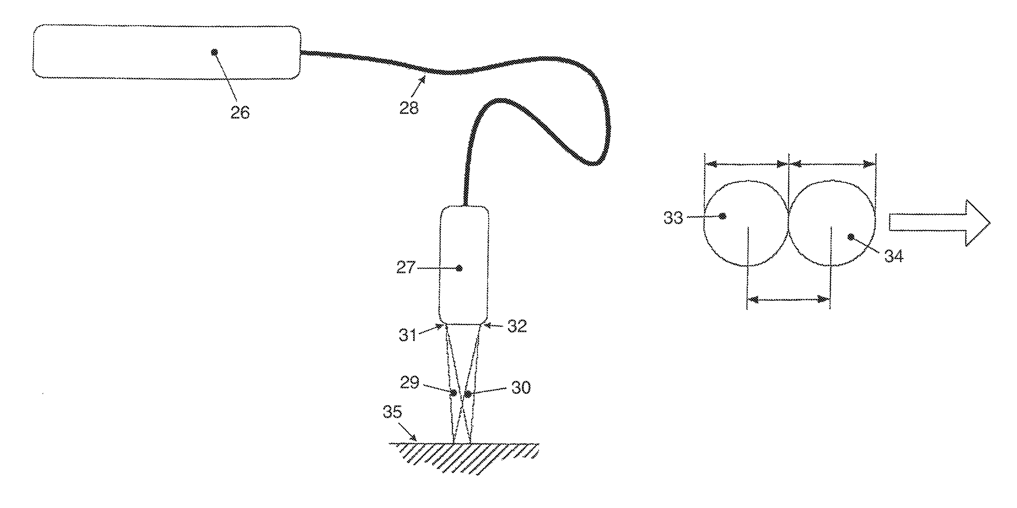
[0013]To improve the welding quality and speed, the edges may for example form an angle of between 0 degrees and 20 degrees with the laser beam, and the parts may be oriented in relation to the laser source so that the outer surfaces of the parts are essentially perpendicular to the laser beam or so that the outer surface forms an angle between 70 degrees and 90 degrees to the laser beam. The focus point of the laser light could be located essentially at the height of the outer surface of the parts, or slightly above or below the outer surfaces. It may be an advantage to position the elements relative to each other so that the gap is of the size of, or slightly smaller than the focus point.
[0016]When the metal evaporates, the gas can be confined in the melt where it causes welding pores and reduces the strength of the welding. Furthermore, the evaporating metal may cause sputtering of the melt and the surface of the welded component may become rugged. To reduce or to avoid these drawbacks, the gap could be provided to allow at least a portion of the gas to defuse from the gap and into the surrounding atmosphere. For that purpose, the gap may preferably be open in the light beam direction outwardly, i.e. the gap may preferably form an opening in the outer surface of the component, and the opening may preferably be at least of the same width or smaller than the size of the laser focal point. A gap with a width in the range of 0.05-0.3 mm has been found suitable for the welding purpose, and a laser with a focus point size of at least 0.15 mm such as at least 0.5 mm or at least 0.8 mm could preferably be selected. To further improve the draining of the gases away from the melt, a passage may be provided in the bottom portion of the welding gap, i.e. opposite the outer surfaces, to conduct the gasses into the inner conduit of the tubular parts.
[0018]The neck and socket may comprise abutting surfaces which are circular in a view cross-sectional to the longitudinal direction, and the parts may, as aforementioned be joined in a friction joint, in a screw joint or in similar ways. In particular, the screw joint may comprise screw threads with a pitch designed to make the preparation of the component for the welding process easy. As an example, the parts may firstly be joined until the edges abut each other, and the pitch of the threads may provide the correct gap based on a specific number of turns of one part relative to the other part. Subsequently, during the welding process, the screw joint may ensure that a minimum distance between the edges remains regardless of potential heat affected deformation of the parts.
[0019]To further ensure the distance, one of the edges may comprise one or more protrusions extending in the longitudinal direction towards the other edge and thereby preventing the two edges from getting closer to each other than the height of the protrusions.

Problems solved by technology

The pores derive from gases which are confined during the crystallization, and these pores, depending upon their number, size and location in the interface, can lead to cracks or prevent good adherence of a surface coating.
One problem related to the reflectivity is that the reflected beam may damage the optics or other parts of the laser welding equipment.
Another problem is that the reflection prevents sufficient deposition of energy to melt the metal.
The light beam reflects back and forth between walls of the gap which results in an increased localised heating of the metal.
One problem, however, is that the gap increases the amount of metal which must be melted and thus decreases the speed at which laser can be advanced in the gap.
If the laser beam energy is increased to solve this problem, a result will typically be an excessive heat input.
If the welding gap is narrowed, the speed may be increased, but in that case, the laser beam must be positioned precisely over the gap, and if the gap is too narrow, the above mentioned problem with reflection of the laser light recurs.
The size of the gap is governed by the position of one part relative to the other, and in practice, it is often difficult to locate the parts precisely.

Method used


Image

  • Laser welding process
  • Laser welding process
  • Laser welding process

Examples


Embodiment Construction

[0030]Referring to FIG. 1, the component 1 is a housing for a valve for controlling a fluid flow. The component is made from a first part 2 and a second part 3 which are prepared to be joined by a welding process. The parts are tubular and form an inner cavity 4. The first part comprises a neck portion 5, which is formed to be inserted in a longitudinal direction, symbolised by the arrow 6 into a complementary socket 7 in the second part. The first part comprises a first edge 8 and the second part comprises a second edge 9. When the neck portion is inserted into the socket, the edges are located adjacent each other with a distance forming a gap between the parts. The distance is shown in FIG. 2 wherein the parts are assembled. A threaded portion 10, 11 is provided for joining the parts preliminary for keeping a fixed mutual position of the parts during welding. When the parts are assembled, they form a valve component with joint sections 12, 13 for soldering the valve into a fluid f...


PUM

PropertyMeasurementUnit
angleaaaaaaaaaa
angleaaaaaaaaaa
angleaaaaaaaaaa

Abstract

The invention provides a method of making a component from first and second parts which are joined in a welding process wherein a laser beam is transmitted in a direction from a laser source and at least partly into a gap. The gap is made between edges of the component, and to enable a faster laser welding process, the laser has a focus point size which is at least of the size of the gap. To enable better control of the width of the gap, the invention further provides a method and components wherein one part is formed with a neck which extends into a complementary socket of the other part to prepare the parts for the welding process. The invention in particular concerns welding of brass.

Description

CROSS REFERENCE TO RELATED APPLICATIONS[0001]This application is entitled to the benefit of and incorporates by reference essential subject matter disclosed in International Patent Application No. PCT / DK2005 / 000821 filed on Dec. 22, 2005; and Danish Patent Application No. PA 2004 02033 filed Dec. 30, 2004.FIELD OF THE INVENTION[0002]The invention relates to a method of making components by laser welding. The components are made from first and second parts, wherein at least one of the parts is made from an alloy which contains metal with a boiling point which is in the range of, or lower than the melting point of the alloy. The parts are joined in a welding process wherein a laser beam is transmitted in a direction from a laser source and at least partly into a gap between first and second edges of the parts. Vapours of metal which boil during the welding process are conducted away from the component via the gap. The invention further relates to a valve made from two components by la...

Claims


Application Information

Patent Timeline
Patent Type & Authority Patents(United States)
IPC IPC(8): B23K26/20B23K26/32F16K27/10
CPCB23K26/285B23K26/3213B23K33/00B23K26/32B23K26/282B23K2103/12
Inventor ORYE, HANS CHRISTIANFUNDER-KRISTENSEN, TORBENMORTENSEN, CHRISTIAN EGGERTVESTERGAARD, ANDERSHE, JIA
Owner DANFOSS AS
Features
  • R&D
  • Intellectual Property
  • Life Sciences
  • Materials
  • Tech Scout
  • Unparalleled Data Quality
  • Higher Quality Content
  • 60% Fewer Hallucinations
Learn More