
Lens barrel unit with lens barrier, and camera

a technology of lens and barrel unit, applied in the field of lens barrel unit, can solve the problems of difficult to provide waterproof or drip-proof function, and achieve the effect of high resistance to external dirt and dust infiltration

Inactive Publication Date: 2011-01-18
CANON KK
View PDF20 Cites 1 Cited by
  • Summary
  • Abstract
  • Description
  • Claims
  • Application Information

AI Technical Summary

Benefits of technology

The present invention provides a lens barrel unit with a lens barrier that is highly resistant to external dirt, dust, and water infiltration. The lens barrier is opened and closed by a pivoting movement of a barrier member, which is driven by a rotary shaft connected to the barrier member. The lens barrel unit with a lens barrier is used in a camera and provides improved protection against external contaminants.

Problems solved by technology

Further, it is difficult to provide a waterproof or drip-proof function for the image pickup apparatus having the lens barrel unit with a lens barrier.

Method used


Image

  • Lens barrel unit with lens barrier, and camera
  • Lens barrel unit with lens barrier, and camera
  • Lens barrel unit with lens barrier, and camera

Examples


Embodiment Construction

[0043]The present invention will now be described in detail below with reference to the drawings showing a preferred embodiment thereof.

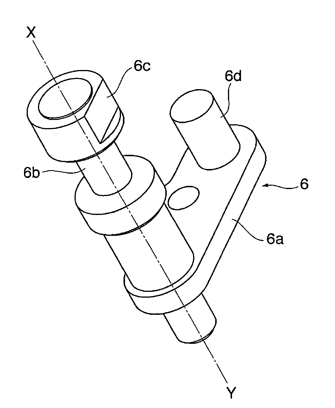
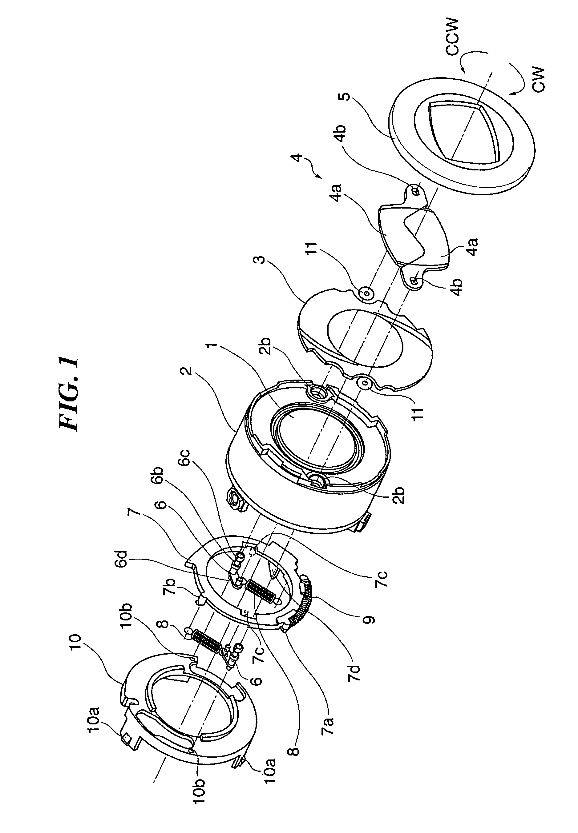
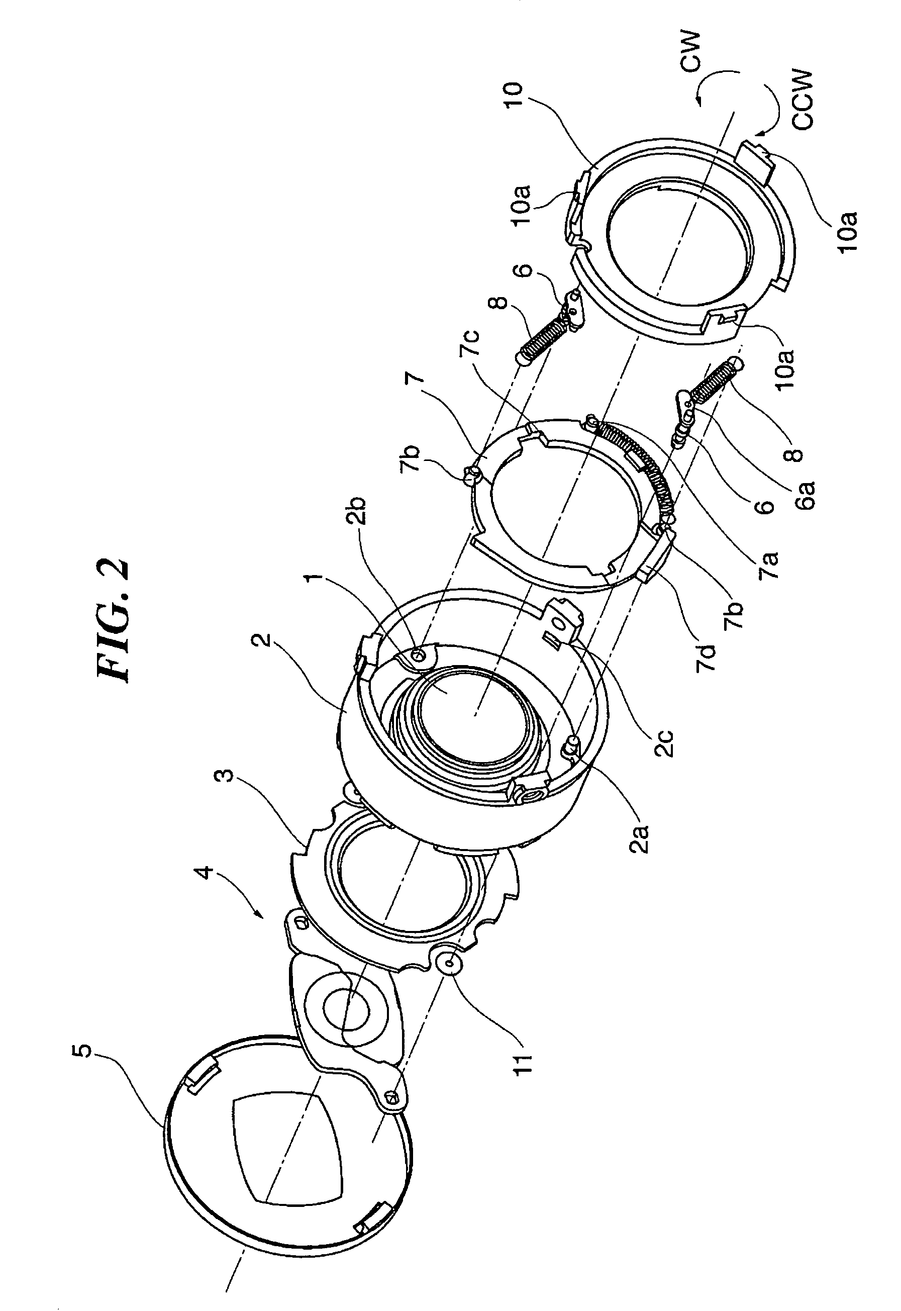
[0044]FIG. 1 is an exploded perspective view showing the construction of a lens barrel unit with a lens barrier according to an embodiment of the present invention, and FIG. 2 is an exploded perspective view of the lens barrel unit in FIG. 1, as viewed from a different direction.FIG. 3 is a perspective view showing the construction of an engaging shaft appearing in FIG. 1. FIGS. 4A to 4C are views schematically showing the positional relationship between an engaging part of a barrier driving ring of the lens barrel unit with a lens barrier in FIG. 1 and a fixed member fixed to a camera body, in which FIG. 4A shows a state where the engaging part of the barrier driving ring is in contact with a sloped surface of the fixed member, FIG. 4B shows a state immediately before the engaging part of the barrier driving ring becomes disengaged from the sloped ...


PUM


Abstract

A lens barrel unit with a lens barrier highly resistant to infiltration of external dirt, dust, and water has a pair of blade members each pivotally movable about a barrier joint hole. Engaging shafts connect to the blade members. The engaging shafts extend coaxially with the barrier joint holes about which the blade members pivotally move. A barrier driving ring applies a driving force to each engaging shafts to rotate it about the corresponding barrier joint hole. The lens barrel has a pair of through holes through which the engaging shafts are rotatably inserted. The engaging shafts are driven for rotation by the driving force transmitted to hook parts of the rotary shaft. The blade members are pivotally movable in the optical axis direction. The lens barrel also serves as a barrier base plate and is disposed between the blade members and the barrier driving ring.

Description

BACKGROUND OF THE INVENTION[0001]1. Field of the Invention[0002]The present invention relates to a lens barrel unit provided with a lens barrier, and a camera incorporating the lens barrel unit.[0003]2. Description of the Related Art[0004]Conventionally, a compact camera, such as a lens shutter camera, is known which is equipped with a lens cap that can be attached and detached to and from the front of a photographic lens. The lens cap is mounted on the camera when the camera is not used, so as to protect the photographic lens or cut external light.[0005]Further, in recent years, many cameras have come to employ a lens barrier provided in a portion of a camera body thereof or of a lens barrel instead of a lens cap, and drivingly control the lens barrier by a barrier driving means provided in the camera body.[0006]In the following, a lens barrel unit provided with the above-mentioned lens barrier will be described with reference to FIG. 5. FIG. 5 is an exploded perspective view of th...

Claims


Application Information

Patent Timeline
Patent Type & Authority Patents(United States)
IPC IPC(8): G03B17/00
CPCG03B11/04G03B17/08G03B11/043
Inventor KOBAYASHI, FUTOSHI
Owner CANON KK
Learn More