
System and method for underwater wireless communication

a wireless communication and wireless communication technology, applied in the field of data communication, can solve problems such as inability to use rf-based communications, interference with underwater data communication performance, and inability to meet the needs of submarines or remotely operated vehicles,

Inactive Publication Date: 2011-01-18
GANGNEUNG WONJU NAT UNIV IND ACAD COOPERATION GROUP
View PDF12 Cites 7 Cited by
  • Summary
  • Abstract
  • Description
  • Claims
  • Application Information

AI Technical Summary

Benefits of technology

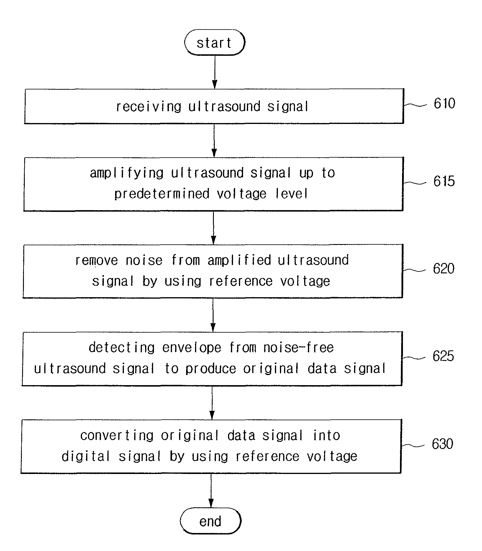
In another embodiment, a method of receiving data in a data communication system having a plurality of sensor, including receiving an ultrasound signal transmitted through water and amplifying the ultrasound signal up to a predetermined voltage level, removing a noise from the amplified ultrasound signal based on a first reference voltage, obtaining an original data signal by detecting a predetermined envelop from the frequency signal without the noise, and converting the original data signal into a digital data signal based on a second reference voltage.

Problems solved by technology

In an underwater environment, RF-based communications may not be appropriate because of a very low transmission range, requiring large antennae and high transmission power.
Unlike a mobile communication in the air, factors such as slow speed of a sound wave (1.5 Km per hour), a narrow usable bandwidth, and reflection by the sea floor or sea surface may interfere with performance of underwater data communication.
The existing submarines or remotely operated vehicles (“ROVs”) may not be practical solutions for measuring and monitoring underwater environments because such systems are not cost-effective.
In addition, no underwater communication systems based on low-power and low-cost is currently available.

Method used


Image

  • System and method for underwater wireless communication
  • System and method for underwater wireless communication
  • System and method for underwater wireless communication

Examples


Embodiment Construction

Since there can be a variety of permutations and embodiments of the present invention, certain embodiments will be illustrated and described with reference to the accompanying drawings. This, however, is by no means to restrict the present invention to certain embodiments, and shall be construed as including all permutations, equivalents and substitutes covered by the spirit and scope of the present invention. Throughout the drawings, similar elements are given similar reference numerals. Throughout the description of the present invention, when describing a certain technology is determined to evade the point of the present invention, the pertinent detailed description will be omitted.

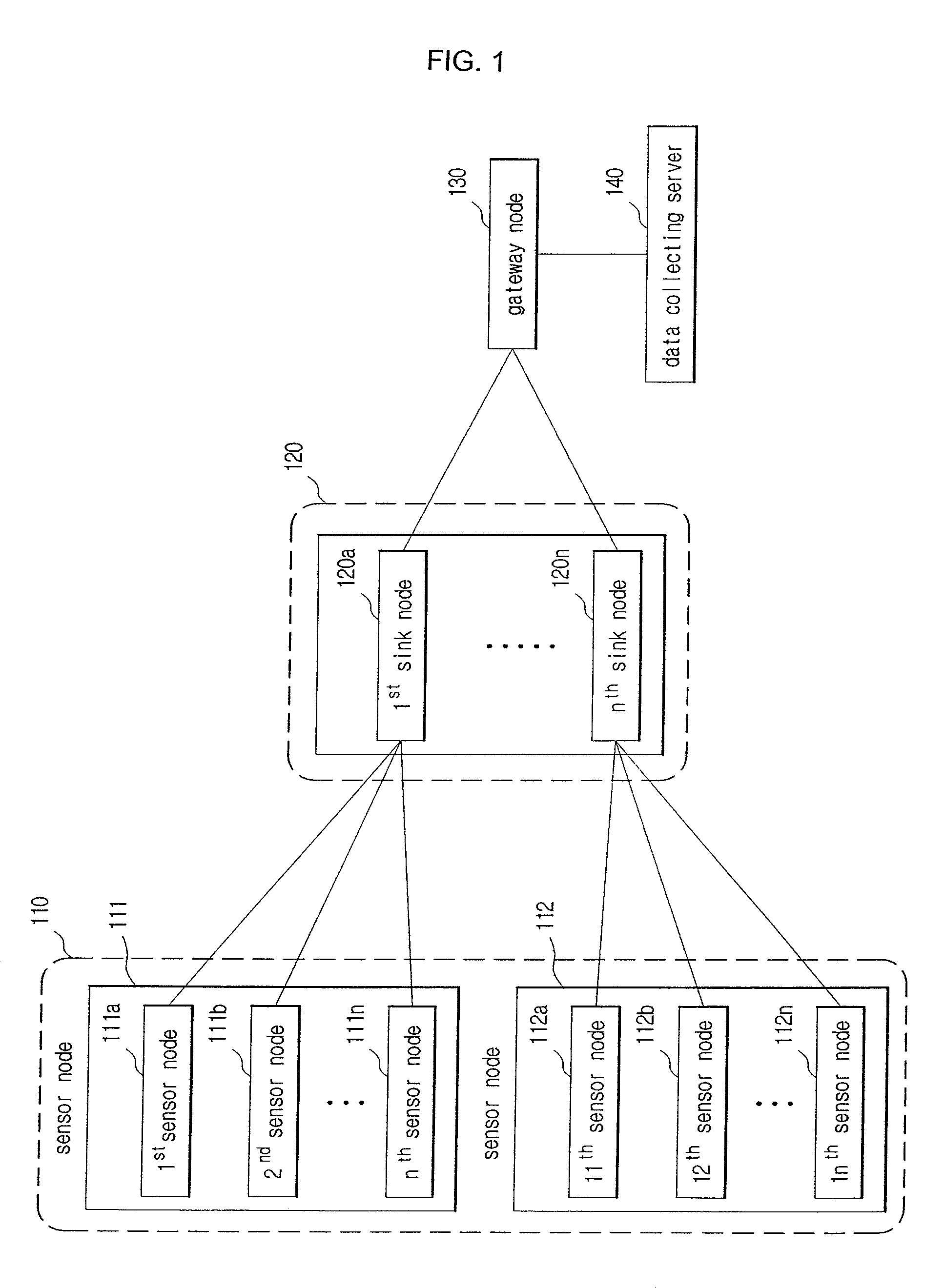
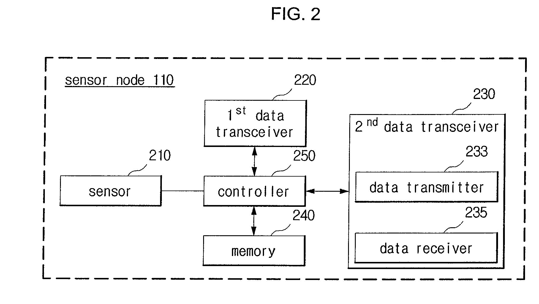
FIG. 1 is a block diagram of an underwater wireless communication system; FIG. 2 is a block diagram of a sensor node; FIG. 3 is a block diagram of a data transmitter; and FIG. 4 is a block diagram of a data receiver. A sensor node 110 operates a data communication system for measuring an underwater env...


PUM


Abstract

An underwater wireless communication system and method includes a sensor node for transforming measured underwater data into ultrasound signals, and transmitting the transformed ultrasound signals and receiving other ultrasound signals.

Description

PRIORITY CLAIMThis application claims under 35 U.S.C. §119 the benefit of the filing date of May 9, 2007 of Korean Patent Application No. 10-2007-0045154, the disclosure of which is incorporated herein by reference in its entirety.BACKGROUND1. Technical FieldThe present invention relates to data communication, and more particularly to an underwater data communication system and method for transmitting data produced by monitoring underwater environments.2. Related ArtIn an underwater environment, RF-based communications may not be appropriate because of a very low transmission range, requiring large antennae and high transmission power. Consequently, underwater communication relies on an acoustic or ultrasonic wave rather than a radio wave. Unlike a mobile communication in the air, factors such as slow speed of a sound wave (1.5 Km per hour), a narrow usable bandwidth, and reflection by the sea floor or sea surface may interfere with performance of underwater data communication. The ...

Claims


Application Information

Patent Timeline
Patent Type & Authority Patents(United States)
IPC IPC(8): H04B11/00
CPCH04B11/00H04B7/24H04B10/00H04W4/18H04W8/08
Inventor AN, SUN-SHINNAM, HEUNG-WOOKU, JUN-HEUNG
Owner GANGNEUNG WONJU NAT UNIV IND ACAD COOPERATION GROUP
Learn More