Mortise/tenon machine

a technology of tenon machine and tenon body, which is applied in the field of tenon machine, can solve the problems of low efficiency and waste of time for work

Inactive Publication Date: 2011-02-08
YANG JACK
View PDF11 Cites 4 Cited by
  • Summary
  • Abstract
  • Description
  • Claims
  • Application Information

AI Technical Summary

Problems solved by technology

It is low efficiency and wastes time for work.

Method used


Image

  • Mortise/tenon machine
  • Mortise/tenon machine
  • Mortise/tenon machine

Examples


Embodiment Construction

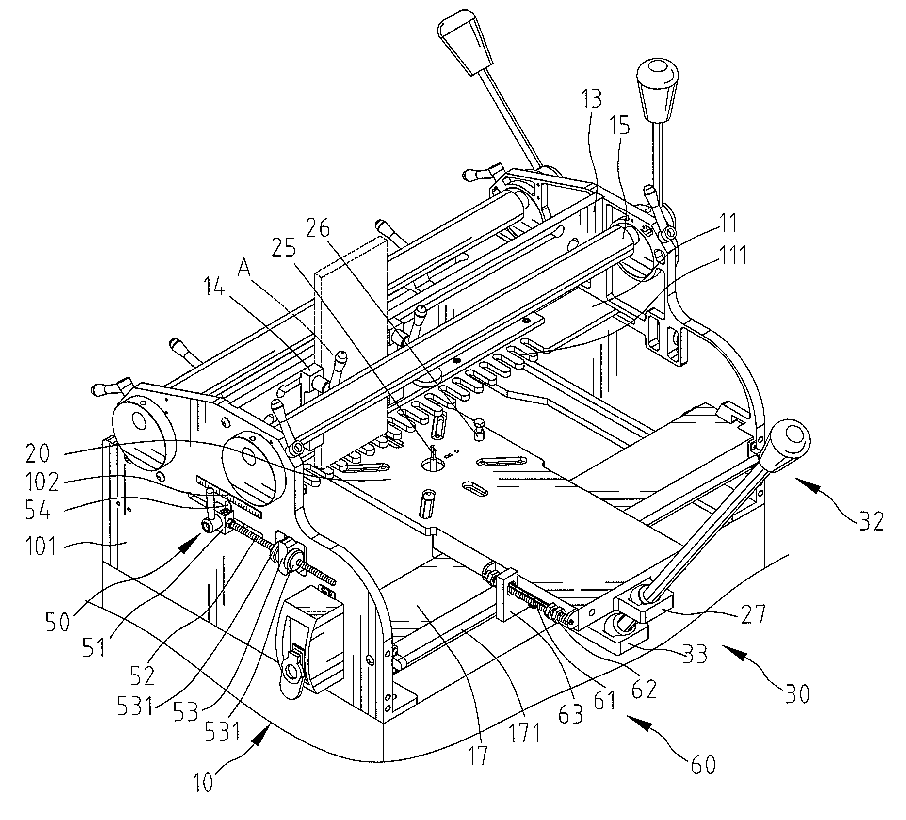
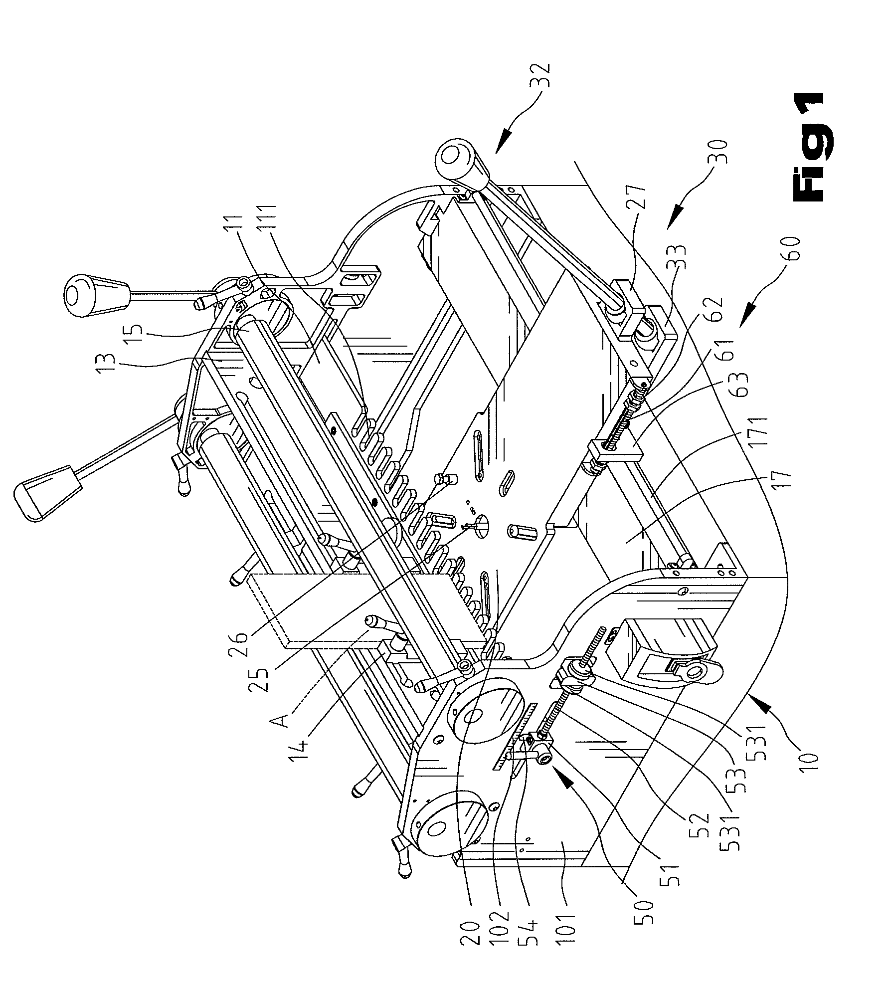
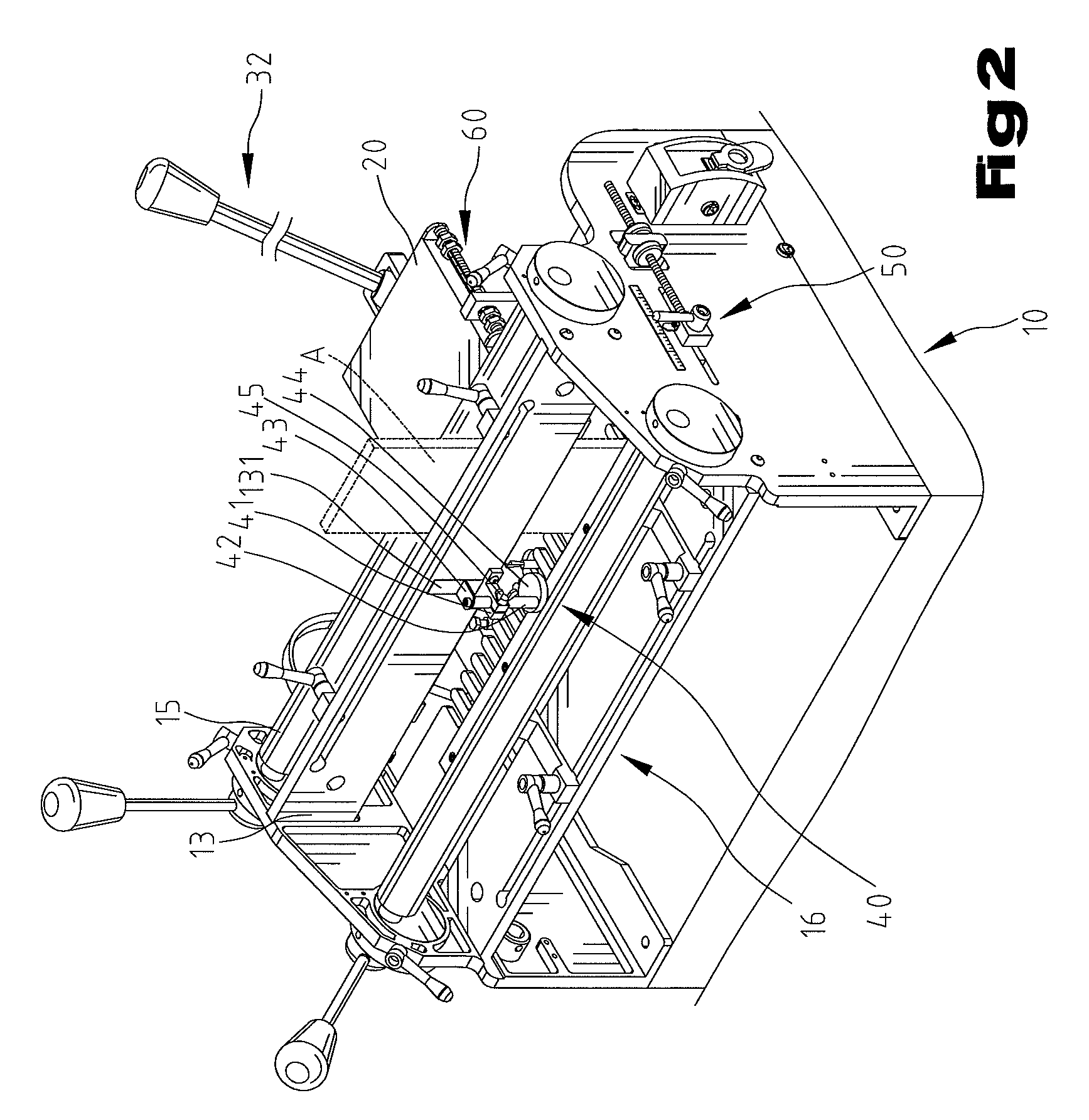
[0018]Referring to FIGS. 1 through 3, a mortise / tenon machine includes a base 10, a working platform 20, a driven member 30, a measuring member 40, two regulating members 50 and a feed arrangement member 60.

[0019]Two side plates 101 are provided on two sides of the top of the base 10, and a guiding plate 11 is slideably installed between the side plates 101 horizontally. A plurality of openings 111 are formed at a side of the guiding plate 11 and spaced equally from one another. An workpiece A (dotted line) shown in FIG. 3 is disposed on the openings 111 vertically and is desired to be cut for forming a plurality of mortises and tenons (not numbered) at an edge thereof. A distance of space between each opening 111 is designed to correspond to that of the mortises and tenons of the workpiece A. A first clamping device 12 is installed at the base 10. The first clamping device 12 includes a support plate 13 affixed between the side plates 101 vertically and adapted to abut against a si...


PUM


Abstract

A mortise / tenon machine has a base which includes two side plates, a guiding plate installed between the side plates transversely and horizontally, numbers of openings formed on a side of the guiding plate, and a rail member installed between the side plates and in the same horizontal position of the guiding plate. A workpiece is slideably disposed on the openings. A sliding base is slideably mounted on the rail member. A working platform includes a bit installed at a first end thereof, with the bit extending from a desired opening, and with another end of the working platform longitudinally disposed on the sliding base.

Description

BACKGROUND OF THE INVENTION[0001]1. Field of the Invention[0002]The present invention relates to a mortise / tenon machine.[0003]2. Description of the Related Art[0004]Referring to FIG. 6, a base (not shown) of a conventional mortise / tenon machine includes a working platform 1 affixed thereon, a guiding plate 2 attached to the working platform 1, a plurality of openings 3 formed on an edge of the guiding plate 2 and equally spaced from one another, a router 4 disposed on a side of the guiding plate 2 and a bit (not shown) installed on the bottom of the router 4. A workpiece (not shown) can be disposed onto the guiding plate 2 above the openings 3. The router 4 slides transversely along the openings 3 and drives the bit to cut mortises and tenons on the workpiece. After finishing cutting, users have to lift a grip 5 on the router 4 to put the router 4 back to its original position. It is low efficiency and wastes time for work.[0005]The present invention will become clearer in light of...

Claims


Application Information

Patent Timeline
Patent Type & Authority Patents(United States)
IPC IPC(8): B27C5/00
CPCB27F1/12
Inventor YANG, JACK
Owner YANG JACK
Why Eureka
Try Eureka