Sprocket

a technology of sprockets and splints, which is applied in the field of splints, can solve the problems of low tooth elasticity, wear on the surface of the load-bearing flank, and teeth still having a high degree of rigidity, and achieve the effect of tooth elasticity

Active Publication Date: 2011-02-08
SRAM
View PDF6 Cites 27 Cited by
  • Summary
  • Abstract
  • Description
  • Claims
  • Application Information

AI Technical Summary

Benefits of technology

[0006]The present invention provides elasticity to individual teeth, permitting redistribution of peak loads from a primary load-bearing tooth to adjoining teeth. The present invention achieves tooth elasticity by providing a plurality of openings proximate the sprocket teeth. Each tooth has a load-bearing flank and a non-load-bearing flank. One of the plurality of openings is arranged relative to one of the plurality of teeth, in one-to-one correspondence therebetween, such that the opening is asymmetrically divided by a radial centerline of the tooth, a first load strip is formed between the opening and the load-bearing flank of the tooth, and a second load strip is formed between the opening and the non-load-bearing flank of the tooth.

Problems solved by technology

The arms allow an elastic deformation of the outer ring portion relative to the inner ring portion when the chain engages the rotary member, but do not provide tooth elasticity.
A disadvantage of this configuration is that the teeth still have a high degree of rigidity.
This leads to very high loading between the load-bearing flank of the tooth and the chain roller, causing wear on the surface of the load-bearing flank especially under cyclical chain loading.
For example, with racing and mountain bikes, thin sprockets arranged close together receive high loads which may cause cracks to form in the teeth.
These cracks may propagate causing the teeth to break.

Method used


Image

  • Sprocket
  • Sprocket
  • Sprocket

Examples


Embodiment Construction

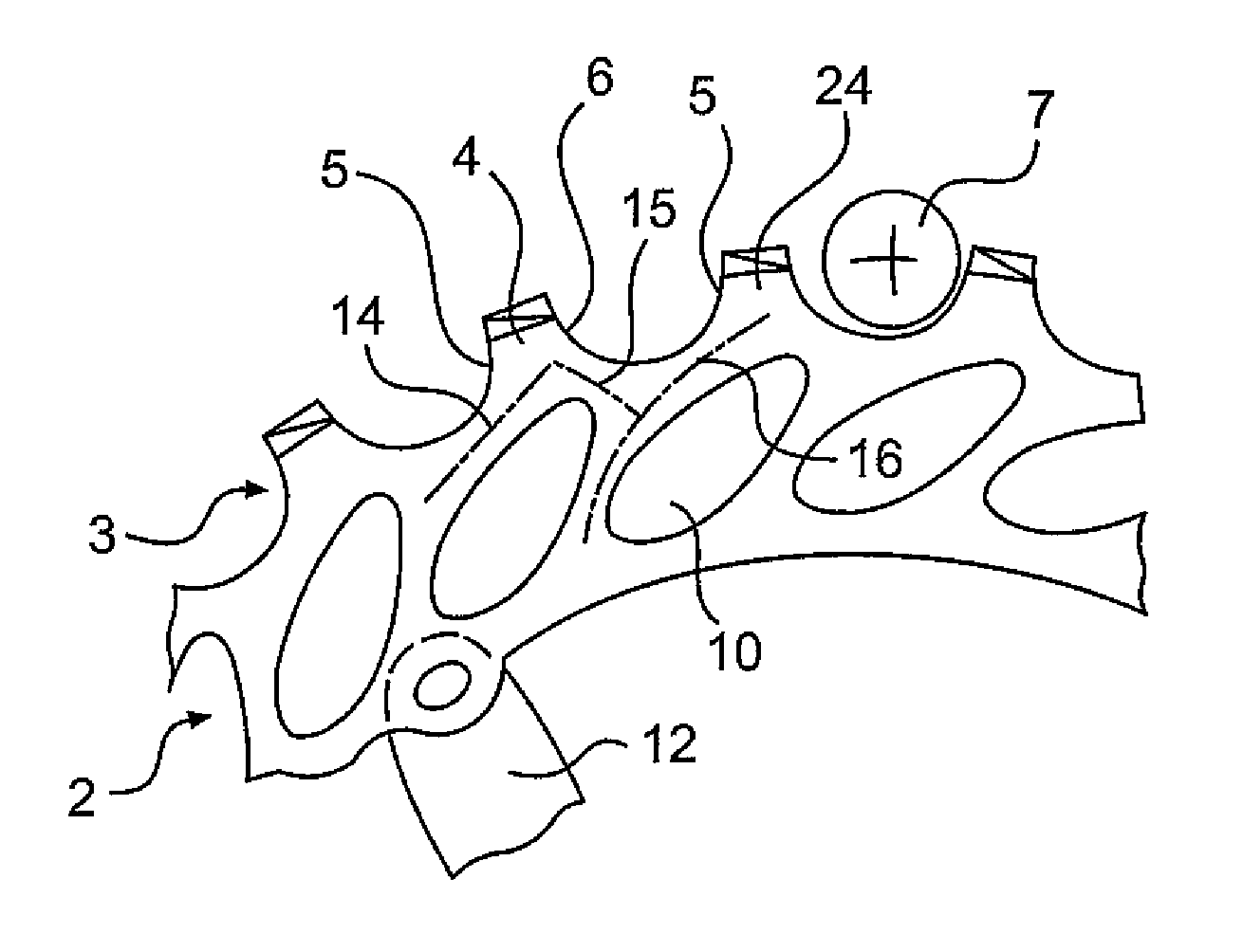
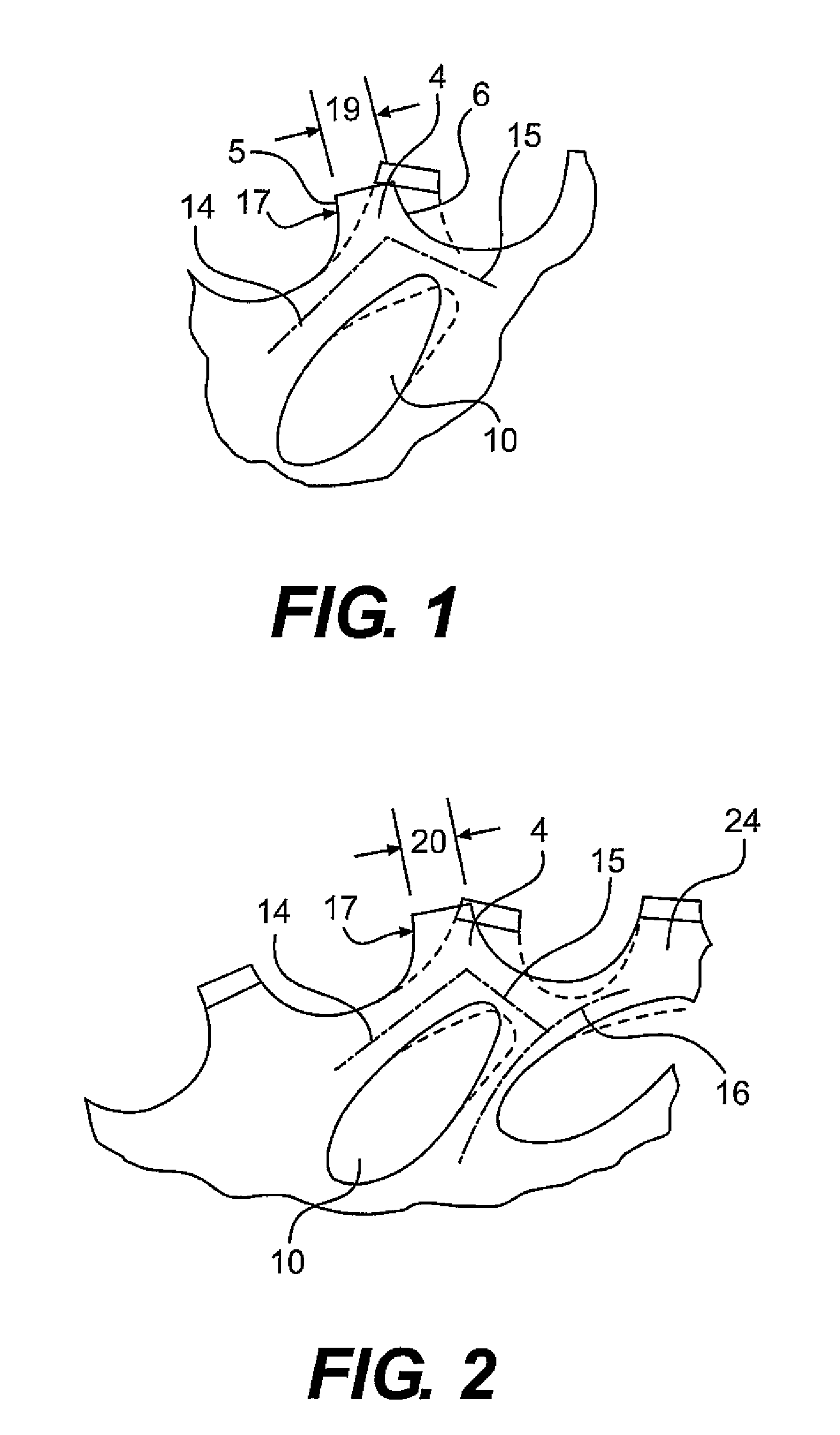
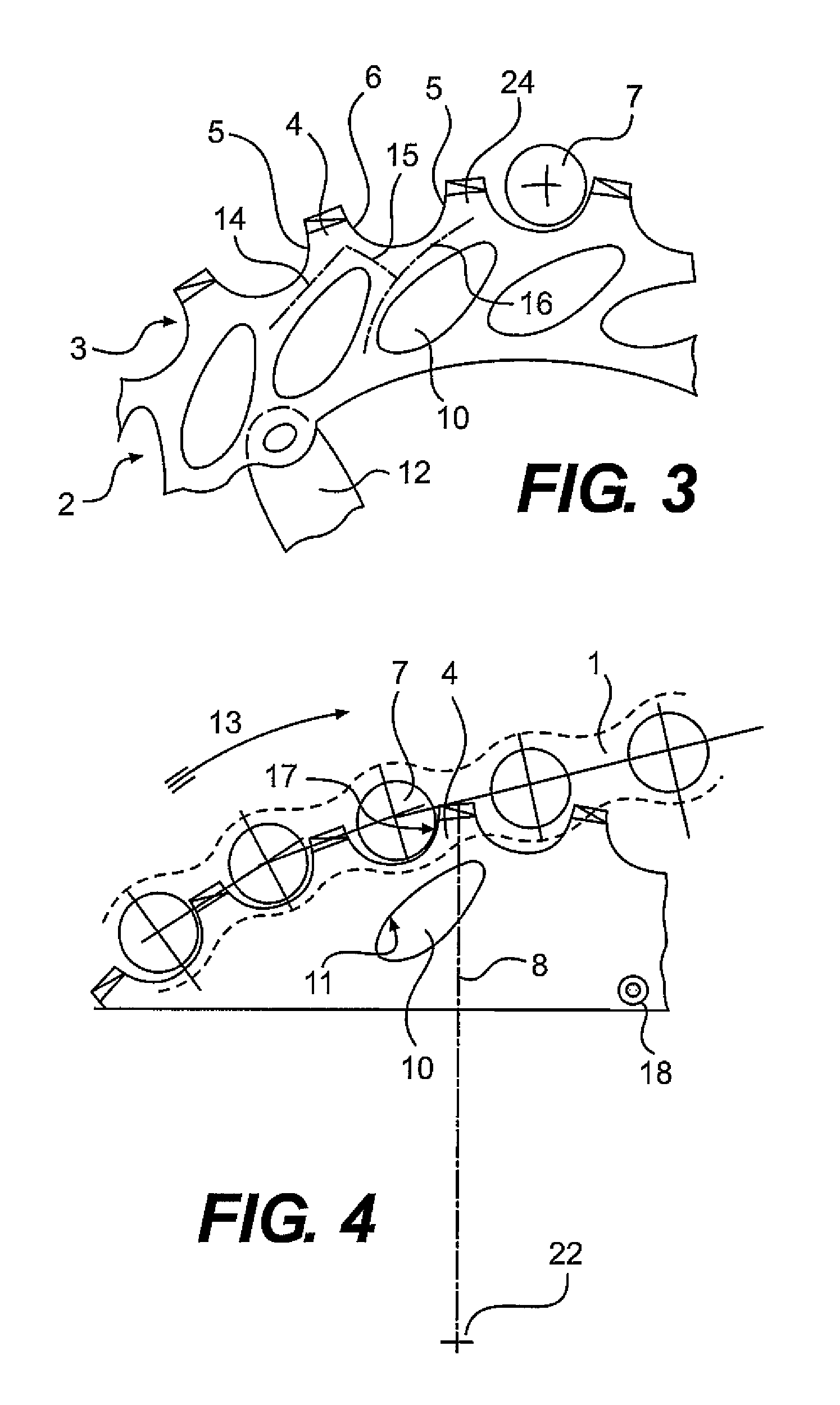
[0014]FIGS. 1-4 illustrate a sprocket 2 for a bicycle according to the present invention. Looking to FIGS. 3 and 4, the sprocket 2 generally includes a plurality of teeth 3 and a plurality of openings 10. The plurality of teeth 3 are disposed around an outer periphery of the sprocket 2. An inner periphery of the sprocket 2 is connected to a drive element 12. Each tooth has a load-bearing flank 5 and a non-load-bearing flank 6.

[0015]FIG. 3 shows an arrangement of the openings 10 over the entire circumference of the sprocket 2. The openings 10 are disposed proximate the plurality of teeth 3. In FIG. 3, each opening 10 is arranged relative to one of the teeth 3, in one-to-one correspondence therebetween, such that the opening 10 is asymmetrically divided by the radial centerline 8 of the tooth 4 (see FIG. 4). The centerline 8 extends through the center 22 of the sprocket and bisects the base of the tooth 4. The opening 10 has an oblong shape and a contour 11. A first load strip 14 is f...


PUM


Abstract

A sprocket for transferring a force between a chain and a drive element that includes a plurality of teeth and a plurality of openings proximate the teeth. Each tooth has a load-bearing flank and a non-load-bearing flank. One of the plurality of openings are arranged relative to one of the plurality of teeth, in one-to-one correspondence therebetween, such that the opening is asymmetrically divided by a radial centerline of the tooth, a first load strip is formed between the opening and the load-bearing flank of the tooth, and a second load strip is formed between the opening and the non-load-bearing flank of the tooth.

Description

BACKGROUND OF THE INVENTION[0001]The present invention relates to sprockets for transmitting a force between a chain and a drive element, and more particularly, to a sprocket having elastic teeth under load.[0002]U.S. Pat. No. 5,980,407 discloses a rotary member in the form of a sprocket or a brake disc for transmitting a drive force or brake force. The rotary member has weight reduction openings disposed between an inner ring portion and an outer ring portion. Arms are formed between the weight reduction openings. The arms allow an elastic deformation of the outer ring portion relative to the inner ring portion when the chain engages the rotary member, but do not provide tooth elasticity.[0003]Additionally, a Shimano cassette CS-7800 is also known that includes multiple sprockets, some of which have circular openings, each of which are disposed under a tooth. These openings are disposed symmetrically relative to their respective tooth centerlines. A disadvantage of this configurati...

Claims


Application Information

Patent Timeline
Patent Type & Authority Patents(United States)
IPC IPC(8): F16H55/12
CPCB62M9/10F16H55/30
Inventor BRAEDT, HENRIK
Owner SRAM
Why Eureka
Try Eureka