
Rolling-ball switch

a ball-vibration switch and rolling ball technology, applied in the field of switches, can solve the problems of limited use of conventional ball-vibration switches, inconvenient use, and inability to ensure the reliable operation of switches b>10/b>

Active Publication Date: 2011-02-08
CHOU
View PDF3 Cites 3 Cited by
  • Summary
  • Abstract
  • Description
  • Claims
  • Application Information

AI Technical Summary

Benefits of technology

"The present invention provides a rolling-ball switch that overcomes the drawbacks of the prior art. The switch includes a housing with at least two receiving sections, a separating member, and conductive balls that roll in the receiving sections. The switch also has first and second terminals that make contact with the conductive balls. The conductive balls can move towards the terminals in one direction only, and the separating member prevents them from moving from one section to the other. This design ensures reliable and efficient operation of the switch."

Problems solved by technology

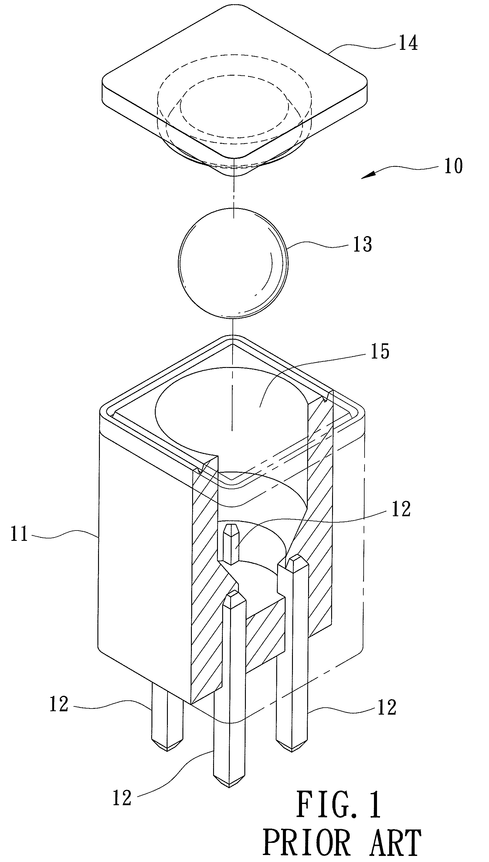
However, since the conductive ball 13 is small and is lightweight, it is possible that the conductive ball 13 may not contact simultaneously the four terminals 12, so that dependable operation of the switch 10 cannot be ensured.
Further, the aforementioned conventional ball-vibration switch 10 is only suitable for use in a vibration-sensing device, and is not suitable for use when tilting of an electronic appliance must be detected.
Hence, use of the conventional ball-vibration switch 10 is limited.

Method used


Image

  • Rolling-ball switch
  • Rolling-ball switch
  • Rolling-ball switch

Examples


Embodiment Construction

[0022]Before the present invention is described in greater detail, it should be noted that the same reference numerals have been used to denote like elements throughout the specification.

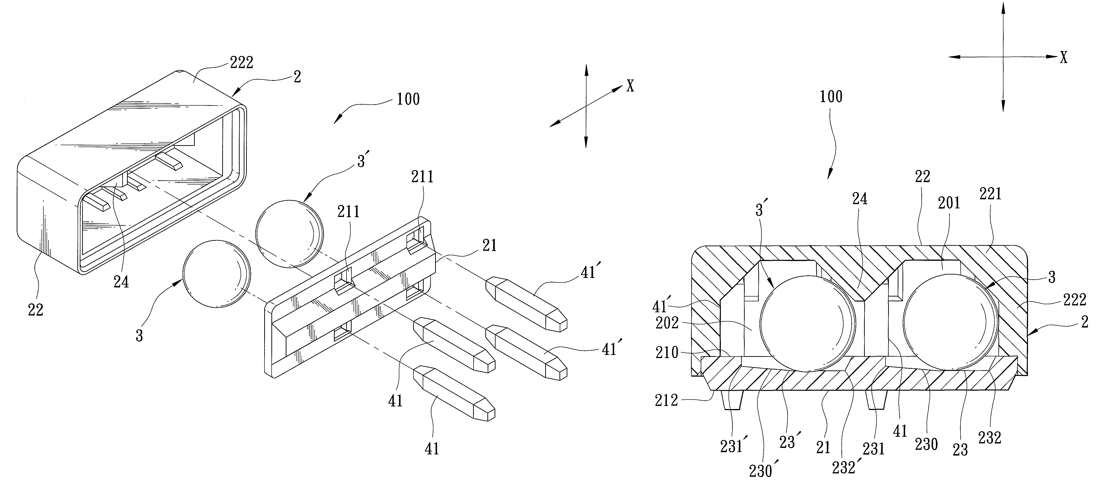
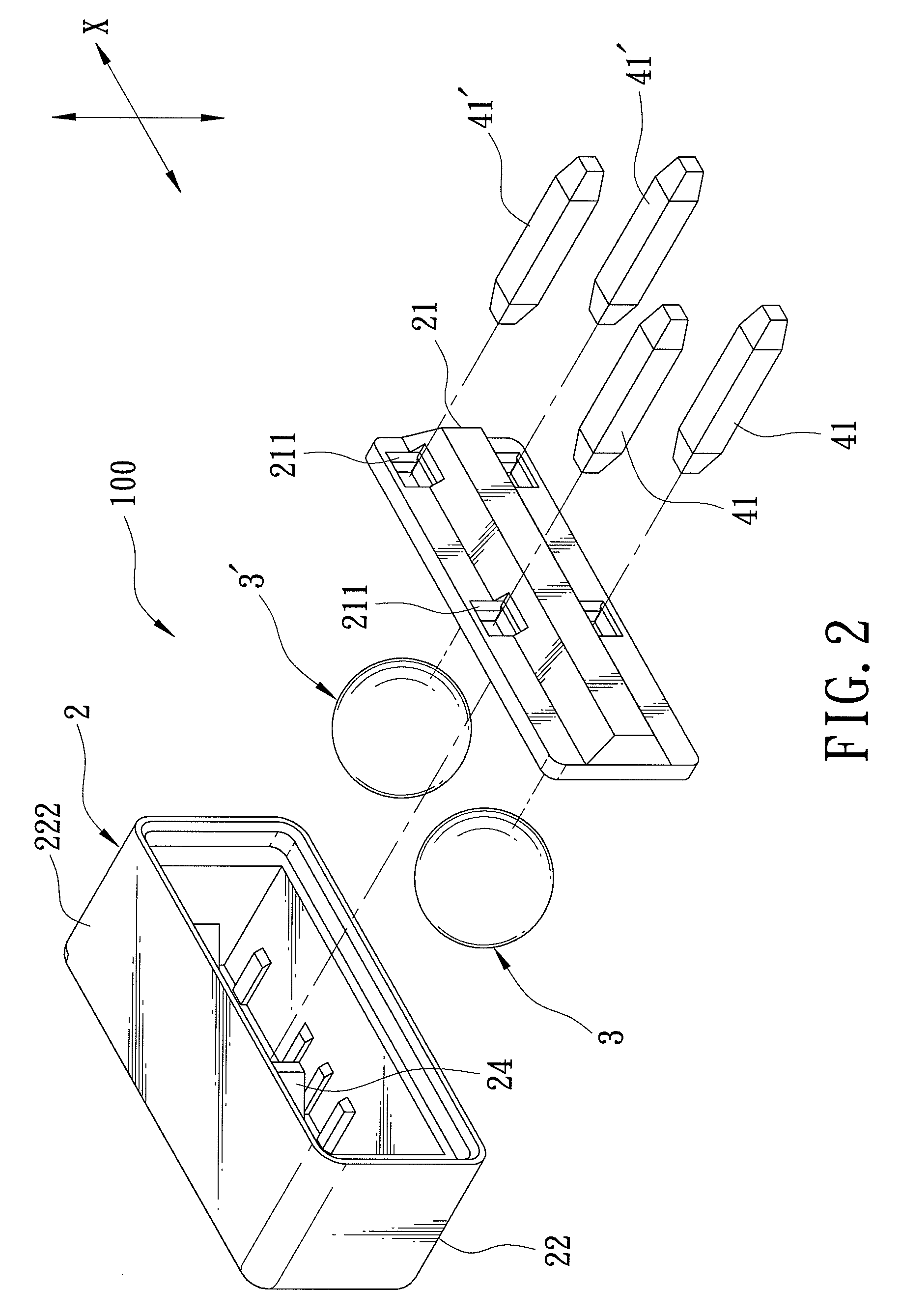
[0023]Referring to FIGS. 2 to 6, a rolling-ball switch 100 according to the first preferred embodiment of the present invention is shown to comprise a housing 2, two conductive balls 3, 3′, a pair of first terminals 41, and a pair of second terminals 41′.

[0024]The housing 2 is made of plastic, and includes a casing part 22, and a plate part 21 that serves as a bottom wall of the housing 2 and that is connected to and that cooperates with the casing part 22 to define two receiving sections 201, 202. The plate part 21 has an inner surface 210 formed with two holding grooves 23, 23′ disposed respectively in the receiving sections 201, 202, an outer surface 212, and two pairs of spaced-apart through holes 211 extending through the inner and outer surfaces 210, 212 thereof and surrounding the holding gro...


PUM


Abstract

A rolling-ball switch includes a housing defining at least two receiving sections, at least one separating member provided in the housing between the two receiving sections, at least two conductive balls disposed rollably and respectively in the receiving sections, a pair of first terminals extending into one of the receiving sections to contact one of the conductive balls, and a pair of second terminals extending into the other one of the receiving sections to contact the other one of the conductive balls. The conductive balls are rollable toward the respective pairs of the first and second terminals in a first direction. The separating member prevents movement of the conductive balls from one of the receiving sections to the other one of the receiving sections.

Description

CROSS-REFERENCE TO RELATED APPLICATION[0001]This application claims priority of Taiwanese Application No. 097146920, filed on Dec. 3, 2008, the disclosure of which is incorporated herein by reference.BACKGROUND OF THE INVENTION[0002]1. Field of the Invention[0003]This invention relates to a switch, more particularly to a rolling-ball switch.[0004]2. Description of the Related Art[0005]Referring to FIG. 1, a conventional ball-vibration switch 10, as disclosed in Taiwanese Patent No. 184124, includes a housing having a casing part 11 and a plate part 14 cooperatively defining a receiving space 15, four spaced-apart terminals 12 extending into the receiving space 15, and a conductive ball 13 disposed in the receiving space 15 to contact the terminals 12.[0006]In use, the conductive ball 13 contacts simultaneously the terminals 12 so as to place the conventional switch 10 in an “ON” state. When an external force is applied to the switch 10 so that the conductive ball 13 moves away from ...

Claims


Application Information

Patent Timeline
Patent Type & Authority Patents(United States)
IPC IPC(8): H01H1/06
CPCH01H35/02H01H35/025H01H35/14H01H35/144H01H2001/0005
Inventor CHOU
Owner CHOU
Learn More