Developing device, image forming apparatus, image forming system, cartridge, developing unit and photoconductor unit

a development device and development cartridge technology, applied in the direction of electrographic process apparatus, instruments, photosensitive materials, etc., can solve the problems of affecting the quality of recording paper, so as to prevent the destruction of the memory unit

Inactive Publication Date: 2011-02-08
SEIKO EPSON CORP
View PDF24 Cites 45 Cited by
  • Summary
  • Abstract
  • Description
  • Claims
  • Application Information

AI Technical Summary

Benefits of technology

[0042]It is another object of the present invention to provide an image forming apparatus with which the storage element of each developing cartridge can be accessed and utilized accurately and quickly, because it is as little as possible susceptible to thermal influences inside the apparatus main unit, and no errors occur in the processing of stored information and there is no drop in communication performance.
[0089]It is a further object of the present invention to effectively prevent the destruction of the memory unit without increasing the number of parts.

Problems solved by technology

In this case, there is the risk that the element cannot communicate properly with the image forming apparatus main unit side.
Here, in such an image forming apparatus, toner development is performed while both the carrying member and the developing roller rotate, so that it is difficult to transfer all of the toner on the circumferential surface of the developing roller to the carrying member or recover it inside the developing cartridge.
Therefore, since the toner is a fine powder, it may scatter / drift from the developing position facing the carrying member to the surroundings and accumulate, and that it pollutes the recording paper or the like.
Therefore, when the memories placed on the developing cartridges are subjected to this thermal influence, then there is the risk that the storage elements placed on the developing cartridges of this image forming apparatus are not only adversely affected, but in the worst case errors may occur during the reading and writing (rewriting) of storage information in those memories.
Furthermore, if the stored information is read out and written by communication in a noncontacting manner with the memories of the developing cartridges from the apparatus main unit side, then there is similarly not only the risk that a communication controller is adversely affected by the heat inside the apparatus main unit, but also that, in the worst case, the communication performance drops.
This problem becomes more significant the more the processing speed of the image formation increases, since the time for which the developing cartridge 2014 stops after the developing is finished becomes shorter.
However, if the communication section communicating with the apparatus main unit side in order to exchange storage information inside the memory 2141 on the side of the developing cartridge 2014 is polluted through contact with drifting toner t, there is the risk of communication faults, regardless of whether this communication section is connected in a contacting manner or in a noncontacting manner.
When accessing the memory 2141 in such a state of connection fault, there is the risk that errors occur in the reading or writing (rewriting) of the information stored in the memory 2141.
Moreover, when the surface of the memory 2141 is polluted, then there is the possibility that for example the outer surface of the memory 2141 is adversely affected by adhering substances.
In this situation, when for example the memory on the outer surface of the developing cartridge or the communication controller is subjected to the thermal influence of the exposing unit, whose temperature has increased, then it is at least adversely affected, and in the worst case, there is the risk that errors may occur in the reading and writing (rewriting) of information stored in this memory, and the communication performance drops.
Therefore, in this image forming apparatus, it is necessary to charge one or both of the members passing on or receiving the toner to a high voltage, and there is the possibility that noise is emitted during the charging or from the charged member.
Therefore, when this noise unnecessarily enters for example an antenna performing communication in a noncontacting manner to rewrite the information stored in the memory placed on the developing cartridge, then there is the risk that the information stored in the memory is deleted or otherwise becomes inaccurate.
Therefore, when too much noise intrudes into this gap from the outside, suitable wireless communication is obstructed.
Therefore, when a developing device is held by a user or the like and mounted to the printer, the developing device is in an instable state until a portion of the developing device is supported by the printer, and there is the risk that the IC memory of the memory unit provided on the outer circumference of the developing device is damaged by inadvertently bumping it into the frame of the printer or the like.
Therefore, there was the problem that the user, for example, has to insert the developing device carefully into the printer.
In such an image forming apparatus, there is the problem that favorable communication is not possible when the memory unit and the communication unit are not arranged at suitable positions, in order to perform communication in a noncontacting manner between the memory unit and the communication unit.
However, since the memory unit and the communication unit communicate by electromagnetic induction, when a magnetic material is present at the inner circumferential surface of the developing container where the memory unit is attached, then there is the problem that when the magnetic flux generated on one side passes through the magnetic material, eddy currents flow in the magnetic material with the magnetic flux at the axial center, the propagated waves are attenuated considerably, and communication may not be possible.
In the above-described case, in which the memory unit communicates contactlessly with the printer, there is the problem that, depending on the antenna characteristics, there is the risk that favorable communication between the memory unit and the printer may not be possible when the temperature of the antenna provided on the printer side increases.

Method used


Image

  • Developing device, image forming apparatus, image forming system, cartridge, developing unit and photoconductor unit
  • Developing device, image forming apparatus, image forming system, cartridge, developing unit and photoconductor unit
  • Developing device, image forming apparatus, image forming system, cartridge, developing unit and photoconductor unit

Examples


second embodiment

Overview of Image Forming Apparatus of Second Embodiment

[0580]The following is an explanation of a second embodiment of the present invention, with reference to the drawings. FIGS. 17 to 21 are diagram showing an embodiment of an image forming apparatus according to the present invention.

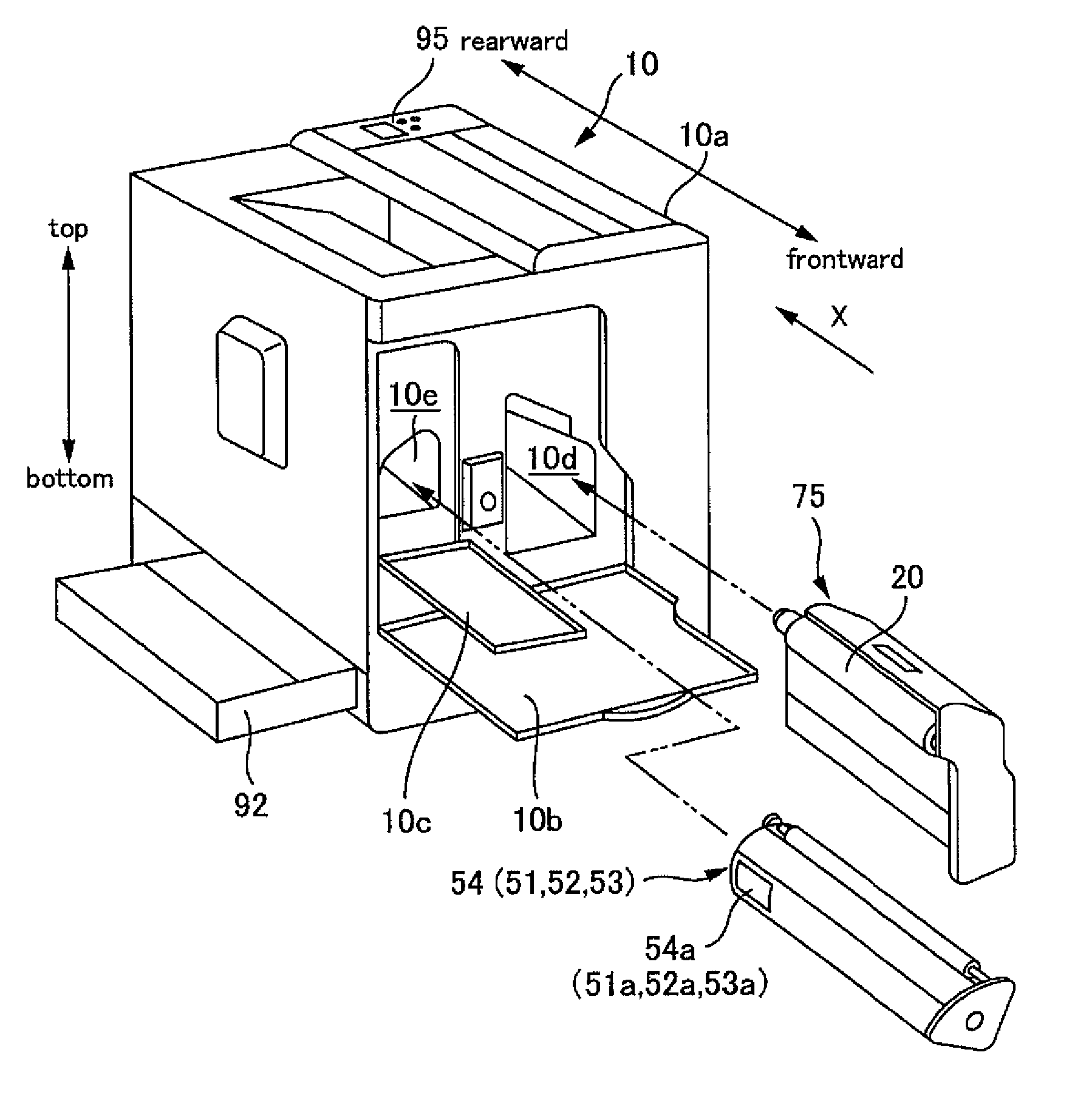
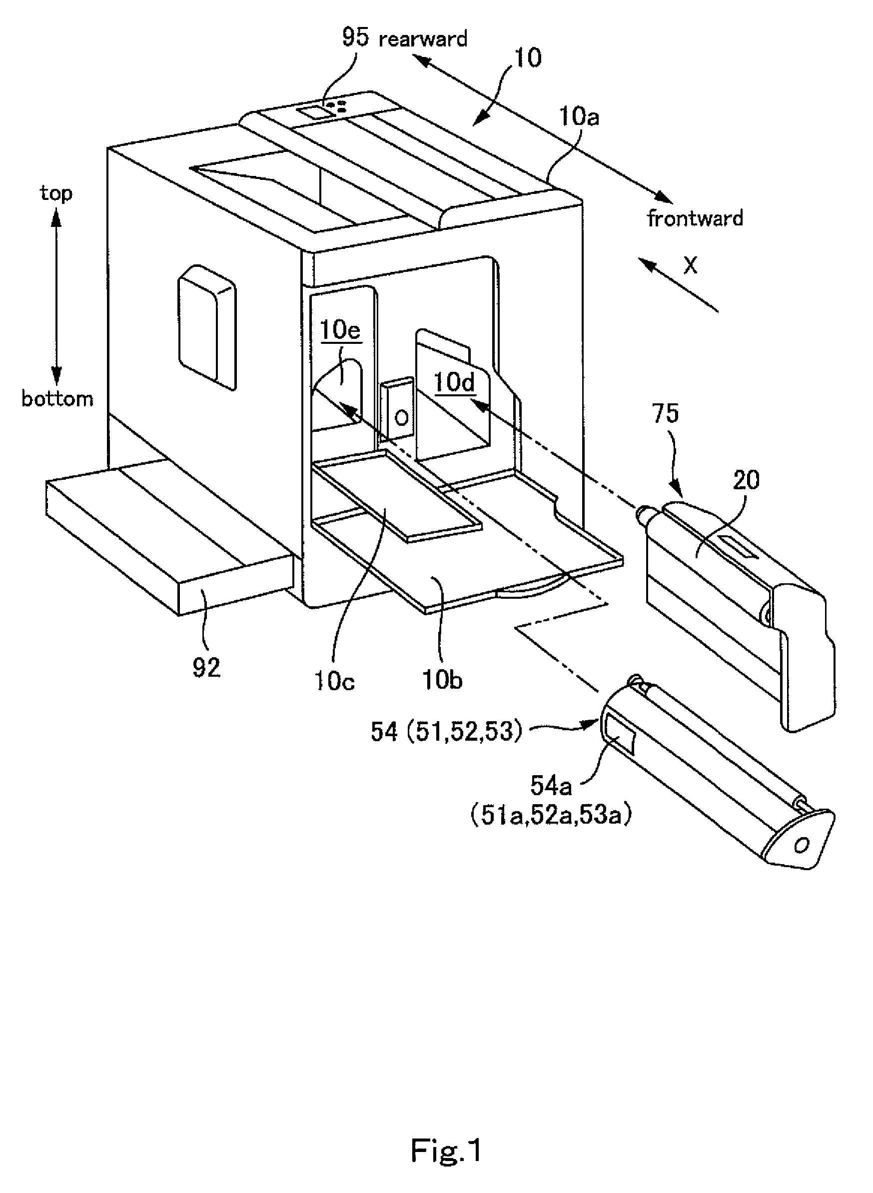
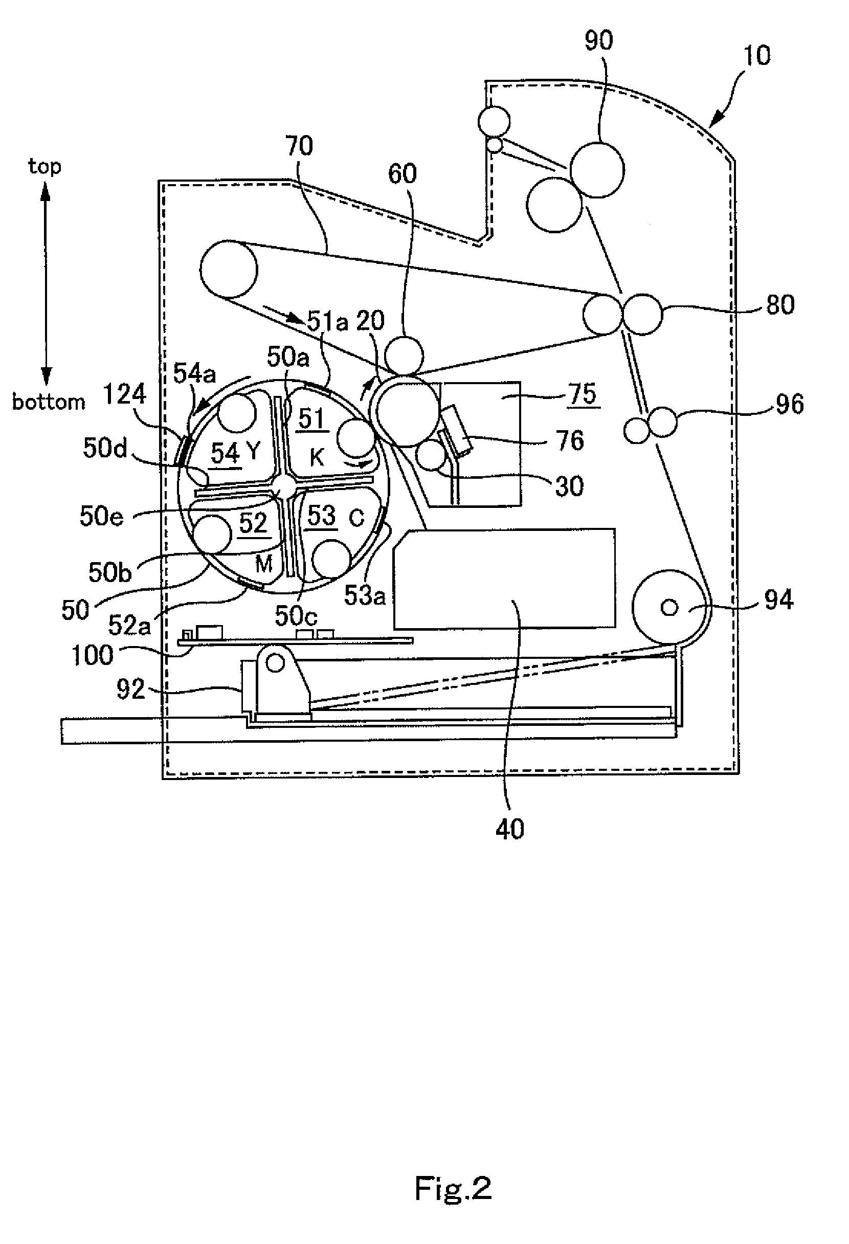
[0581]In FIG. 17 and FIG. 18, the image forming apparatus is a printer that is used by connecting it to an external device such as a personal computer PC that creates and outputs images of text or the like. This image forming apparatus includes an image recording device 1010 that records and forms images on one side or both sides of recording paper (recording medium) through electrophotography by reading in image data of text or the like to be image-formed, a paper carrying device 1020 that carries a plurality of stacked recording papers to the image recording device 1010 and carries the recording paper on which an image has been recorded and formed out of the apparatus, stacking the recording paper...

third embodiment

Overview of Image Forming Apparatus of Third Embodiment

[0613]The following is an explanation of a third embodiment of the present invention, with reference to the drawings. FIGS. 24 to 28 are diagrams showing an embodiment of an image forming apparatus according to a third embodiment of the present invention.

[0614]In FIG. 24 and FIG. 25, the image forming apparatus is a printer that is used by connecting it to an external device such as a personal computer PC that creates and outputs images of text or the like. This image forming apparatus includes an image recording device 2010 that records and forms images on one side or both sides of recording paper (recording medium) through electrophotography by reading in image data of text or the like to be image-formed, a paper carry device 2020 that carries a plurality of stacked recording papers to the image recording device 2010 and carries the recording paper on which an image has been recorded and formed out of the apparatus, stacking t...

fourth embodiment

Overview of Image Forming Apparatus of Fourth Embodiment

[0644]The following is an explanation of a fourth embodiment of the present invention, with reference to the drawings. FIGS. 31 to 36 are diagrams showing an embodiment of an image forming apparatus according to the present invention.

[0645]In FIG. 31 and FIG. 32, the image forming apparatus is a printer that is used by connecting it to an external device such as a personal computer PC that creates and outputs images of text or the like. This image forming apparatus includes an image recording device 3010 that records and forms images on one side or both sides of recording paper (recording medium) through electrophotography by reading in image data of text or the like to be image-formed, a paper carry device 3020 that carries a plurality of stacked recording papers to the image recording device 3010 and carries the recording paper on which an image has been recorded and formed out of the apparatus, stacking the recording paper, ...


PUM


Abstract

A developing device that can be mounted to and dismounted from a mounting and dismounting section provided in an image forming apparatus main unit, the developing device includes: a developing device main unit; a positioning member for positioning the developing device main unit with respect to the mounting and dismounting section by engaging the mounting and dismounting section when the developing device is mounted to the mounting and dismounting section, the positioning member being fixed on a one end side in a longitudinal direction of the developing device main unit; a coupling member that is to be coupled to the mounting and dismounting section when the developing device is mounted to the mounting and dismounting section, the coupling member being attached to the other end side in the longitudinal direction of the developing device main unit in such a manner that its relative position to the developing device main unit can be changed; and an element capable of communication in a noncontacting manner with the image forming apparatus main unit side when the developing device is mounted to the mounting and dismounting section, the element being provided at the one end side in the longitudinal direction of the developing device main unit.

Description

TECHNICAL FIELD[0001]The present invention relates to developing devices, image forming apparatuses, image forming systems, cartridges, developing units and photoconductor units.BACKGROUND ART[0002]Image forming apparatuses such as laser beam printers are well known. Such image forming apparatuses include, for example, an image bearing member for bearing a latent image, and a developing device for developing the latent image borne on the image bearing member with a developer, wherein the developing device can be mounted to and dismounted from a mounting and dismounting section provided in the image forming apparatus main unit. When an image signal or the like is sent from an external device, such as a host computer, to this image forming apparatus, the developing device is positioned at the developing position opposite to the image bearing member, a developer image is formed by developing the latent image borne on the image bearing member with the developer inside the developing dev...

Claims


Application Information

Patent Timeline
Patent Type & Authority Patents(United States)
IPC IPC(8): G03G15/00
CPCB41J29/02B41J29/13G03D13/002G03G15/0863G03G15/0896G03G21/1647G03G21/1676G03G21/185G03G21/1882G03G21/206G03G2221/163G03G2221/1654G03G2221/1815G03G2221/1823
Inventor SHIROKOSHI, JUNJIOKAMOTO, KATSUMISEGAWA, YUICHIMIYAMOTO, SATORUYAMADA, YOICHIHORI, YASUSHIGEFUKUMOTO, TAKATOMO
Owner SEIKO EPSON CORP
Why Eureka
Try Eureka