Light bulb socket adapter

a technology for adapters and light bulbs, applied in the direction of non-rotary current collectors, electrical discharge lamps, coupling device connections, etc., can solve the problems of energy-saving light bulbs, narrow lighting range of adapters, and prone to blind zones

Inactive Publication Date: 2011-02-15
LIN MING ING
View PDF2 Cites 4 Cited by
  • Summary
  • Abstract
  • Description
  • Claims
  • Application Information

AI Technical Summary

Benefits of technology

[0006]The main objective of the present invention is to provide a light bulb socket adapter, which enables to orient at least one light bulb mounted thereon to irradiate in a desired direction respectively and provide the adaptability to mount a bayonet-type bulb to a conventional screw-type bulb socket without requiring an additional adapter.

Problems solved by technology

Although such socket adapter addresses a solution to alternatively replace a regular screw-type socket, it brings up another issue that some energy-saving light bulbs and LED light bulbs mounted to the socket adapter have a narrow lighting range because of their nature being a pointing light source instead of being a radiating light source, e.g. an incandescent bulb.
The light bulbs of conventional lighting products are mounted fixedly and are prone to a blind zone.
However, such structures usually don't take the function of socket adapter into account.

Method used


Image

  • Light bulb socket adapter
  • Light bulb socket adapter
  • Light bulb socket adapter

Examples


first embodiment

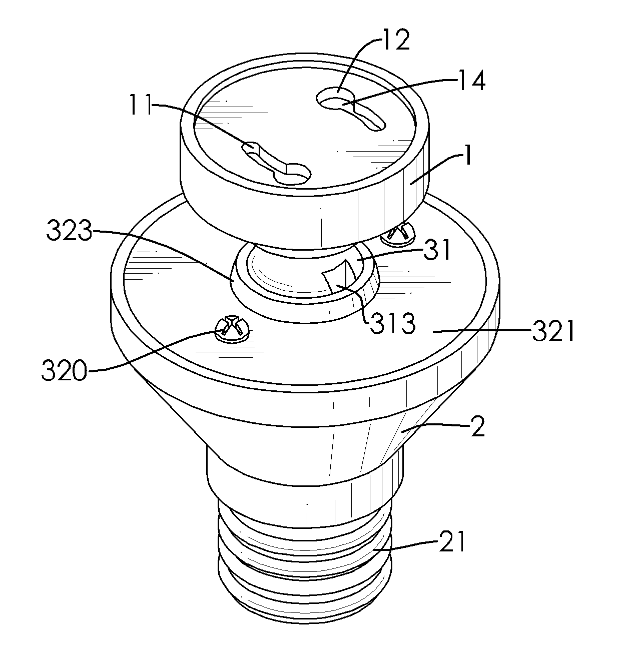
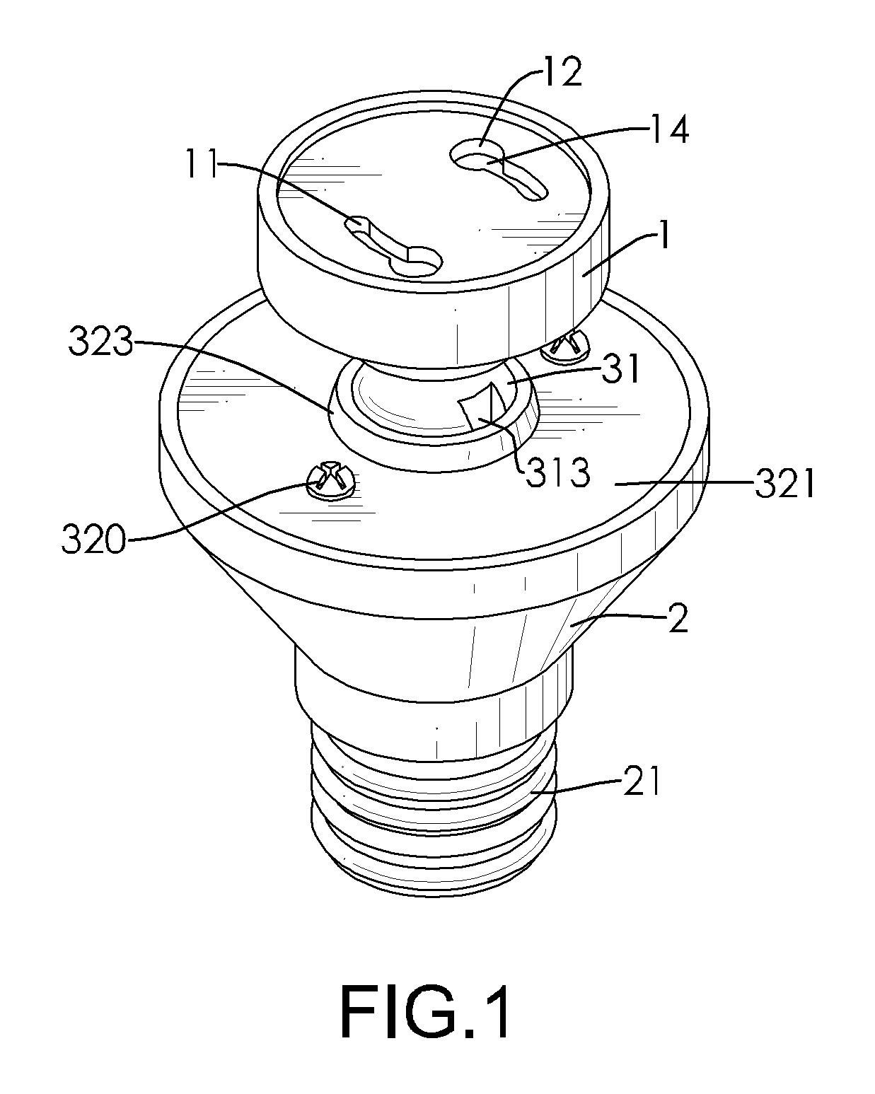
[0022]With reference to FIGS. 1, 2 and 3, a light bulb socket adapter in accordance with the present invention includes a lamp holder (1), an adapter base (2) and an oscillating connection assembly (3).

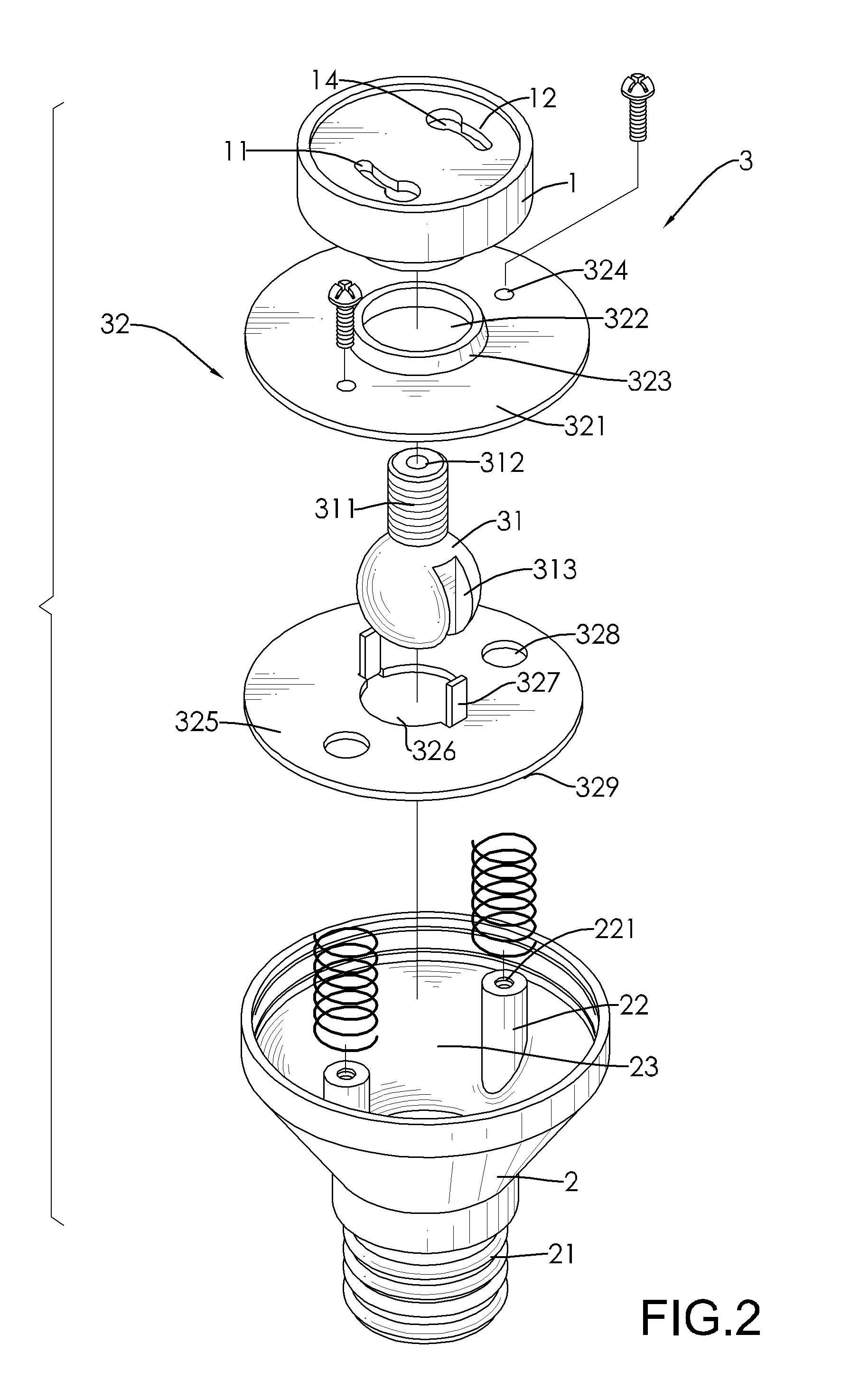
[0023]The lamp holder (1) has a bayonet-type socket to be inserted by an LED bulb or a bayonet-type energy-saving bulb. The adapter base (2) has a large end, a small end and two positioning pins (22). The small end has a base (21) of a screw-type bulb having a ring contact (211) and a tip contact (212) is fitted in a screw-type socket, and an open chamber (23) is formed at the large end. The two positioning pins (22) are mounted inside the chamber of the adapter base. Each of the positioning pin (22) has a positioning hole (221), which is a sunken hole therein.

[0024]With reference to FIG. 1, FIG. 2 and FIG. 3, the lamp holder (1) is oscillatingly mounted to the adapter base (2) through an oscillating connection assembly (3). The lamp holder (1) has a top, a bottom, an inner chamber, t...

second embodiment

[0029]Differing from the light bulb socket adapter as shown in FIG. 1, with reference to FIG. 6, a light bulb socket adapter in accordance with the present invention has three lamp holders (1) mounted on a base adapter (2). In the present embodiment, to correspond to the three lamp holders (1), three first openings (322) and three annular flanges (323) are formed on the first cover (321), three second openings (326) are formed on the second cover and two tabs are mounted to a circumference of each of the second openings, and two slots (313) are formed on each of the balls (31). The lamp holders (1) are so located that any lamp holder (1) having a bulb thereon doesn't conflict with other lamp holder (1) having a bulb thereon while the lamp holder (1) are oscillated. Such design satisfies the requirement of brighter luminance and various lighting directions of bulbs.

[0030]In contrast to prior art, the present invention enables a bayonet-type bulb to be applied to a screw-type socket w...


PUM


Abstract

A light bulb socket adapter includes an adapter base and at least one lamp holder. The adapter base includes a base having a ring contact and a tip contact. The at least one lamp holder is oscillatingly mounted to the adapter base through an oscillating connection assembly. The oscillating connection assembly has a ball-holding mechanism mounted on an end opposite to the base of the adapter base, and at least one ball fixedly connected with the respective lamp holder and oscillatingly engaged with the ball-holding mechanism. The present invention allows the light bulb mounted thereon to irradiate in a desired direction and a bayonet-type bulb to be mounted in a conventional screw-type socket without requiring an additional socket adapter.

Description

BACKGROUND OF THE INVENTION[0001]1. Field of the Invention[0002]The present invention relates to a light bulb socket, and more particularly to a light bulb socket adapter adjusting the lighting direction of a light bulb mounted thereon.[0003]2. Description of Related Art[0004]To keep abreast with the constant pursuit of higher living standard and everchanging sense of style, lighting plays an indispensable role in daily life of people. Because of its critical effect dominating interior decorating and gigantic market demand behind that, countless lighting products and accessories emphasizing practical or aestheic consideration are ceaselessly introduced to meet customer's demand in the extremely competitive market.[0005]Due to the energy-saving advantage, LED light bulb and energy-saving bulb have been widely accepted by customers nowadays. LED light bulb has few pins to be inserted in the corresponding LED bulb socket, a bayonet-type socket. Such bayonet-type socket differs from the...

Claims


Application Information

Patent Timeline
Patent Type & Authority Patents(United States)
IPC IPC(8): H01R39/00
CPCH01R33/94H01R33/06H01R33/22
Inventor LIN, MING-ING
Owner LIN MING ING
Why Eureka
Try Eureka