Assembly of a flash-lamp string system

Inactive Publication Date: 2005-07-07
KUO CHENG JI
View PDF3 Cites 2 Cited by
  • Summary
  • Abstract
  • Description
  • Claims
  • Application Information

AI Technical Summary

Benefits of technology

[0012] Yet another object of the present invention is to provide a flash-lamp system, in which the lamp assemblies can be furnished with several winkle sockets to be mounted with several winkle bulbs respectively. By means of the thermal cut-out effect, the bulb will be turned off; in that case, the rest bulbs in the lamp assemblies with gain more current; the alternate turning-off effect of several bulbs will provide an alternate variation of brightness among the bulbs.

Problems solved by technology

The bulb sockets of the different flash-lamp strings are the same in outer shape; however, the bulbs of the two different flash-lamp strings can not be plugged in the bulb sockets of different flash-lamp strings so as to prevent from causing over load of power supply.

Method used


Image

  • Assembly of a flash-lamp string system
  • Assembly of a flash-lamp string system
  • Assembly of a flash-lamp string system

Examples


Embodiment Construction

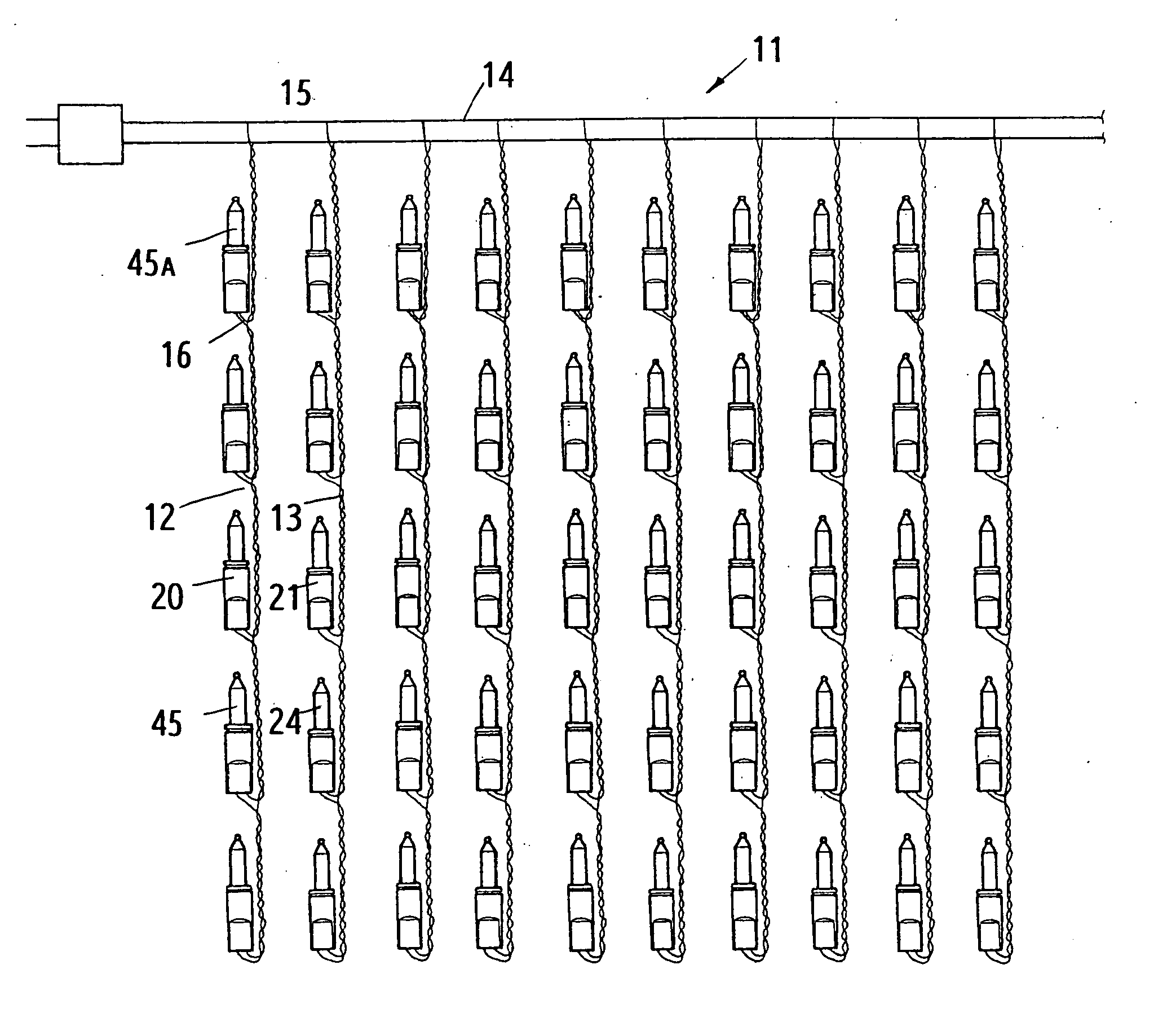
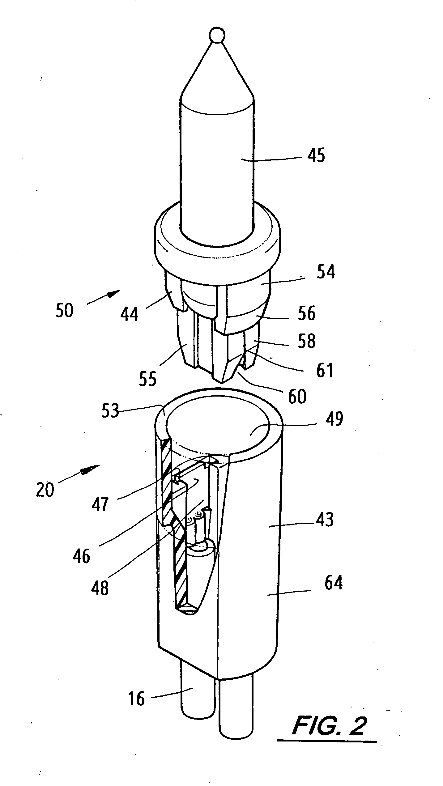
[0024] This invention relates to a flash-lamp string; as shown in FIG. 1, the flash-lamp system 11 comprises a plurality of flash-lamp strings 12 (or 13) connected, in parallel, with a main power-supply cable 14. The lamp assemblies 20 (or 21) of every flash-lamp strings 12 (or 13) are designed in the same shape. A short power-supply wire 16 is used for connecting, in series, between two lamp assemblies 20 (or 21); then, a long power-supply wire 15 is used for connecting the last lamp assembly with the main power-supply cable 14. A plurality of flash-lamp string 12 (or 13) are twisted or knitted into a long lamp string or a suitable lamp string.

[0025] A plurality of flash-lamp strings 12 and 13 can be knitted into a complex flash lamp system 11. The bulbs 45 (or 24) in every lamp assembly 20 (or 21) of one flash-lamp string 12 (or 13) are classified into different kinds by means of the quantity, the resistance value, and the shape of the bulbs. If the first flash-lamp string 12 is ...


PUM


Abstract

An assembly of a flash-lamp string system comprising a plurality of flash-lamp strings connected in series so as to form into an elongate lamp string; the elongate lamp string includes at least two different flash-lamp strings in terms of flashing type; the outer shape of the two different flash-lamp strings is the same; the bulb socket and the bulb assembly of every aforesaid flash-lamp string can be mounted together within the same flash-lamp string; in other words, the bulb socket and bulb assembly can not be exchanged with that of the different type of flash-lamp string in order to avoid overload of power supply.

Description

BACKGROUND OF THE INVENTION [0001] 1. Field of the Invention [0002] This invention relates to a flash-lamp system, and particularly to a flash-lamp string comprising two different types of flash-lamp strings. [0003] 2. Description of the Prior Art [0004] In a conventional flash-lamp string usually comprises a separate power-supply wire connected with a plurality of lamp sockets which are connected in series; the last lamp socket on the end of the string is connected with a separate power-supply wire; then, the two separate power-supply wires are twisted together to form into a lamp string; each socket is mounted with a bulb; the lamp string is used as a decoration; every lamp string is mounted with a thermal cut-out bulb so as to have all the rest bulbs turned on and off continuously, i.e., to provide a flash effect. A plurality of lamp strings can be connected in parallel, and twisted into an elongate lamp string; such an elongate lamp string is referred as a regular flash-lamp str...

Claims


Application Information

Patent Timeline
Patent Type & Authority Applications(United States)
IPC IPC(8): F21S4/00F21V19/00
CPCF21V19/0005F21S4/001F21S4/10
Inventor KUO, CHENG-JI
Owner KUO CHENG JI
Why Eureka
Try Eureka