
Methods and apparatus for controlling hazardous and/or flammable materials

a technology for applied in the field of methods and apparatus for controlling hazardous and/or flammable materials, can solve the problems of only being exposed to the threat of ignition and resultant flame spread, material can injure or kill, and hundreds of thousands of vehicular accidents a year on american highways

Active Publication Date: 2011-03-15
FIRETRACE USA LLC
View PDF5 Cites 15 Cited by
  • Summary
  • Abstract
  • Description
  • Claims
  • Application Information

AI Technical Summary

Problems solved by technology

When the unsafe materials become uncontained, however, the materials can injure or kill, such as when the container is damaged and the material escapes.
For example, hundreds of thousands of vehicular accidents occur each year on American highways.
This duration, however, may be long enough to ignite the fuel mist into a possible explosion, or more likely a fireball that ignites a developing pool of fuel surrounding the vehicle and create a more serious threat.
In many cases, the threat of ignition and resultant flame spread only exists for the instant that the sparks from the impact event remain.
These high profile examples often lead to spectacular fire events and the higher rates of burn injuries and fatalities when they occur, and have resulted in national discussions on how to prevent their continued occurrence.
Unfortunately, most fire protection technologies are impractical for general highway vehicle or other consumer use, due to cost, complexity, reliability problems, and substantial weight increases.
As a result, little has been done to prevent such events in the future.
In particular, military aircraft that are impacted by anti-aircraft projectiles can develop fires in adjoining bays adjacent to fuel tanks onboard the aircraft.
The fuel leaking or spraying from a penetrated tank encounters ignition sources, such as burning incendiary particles deposited by the projectile in the adjoining bay, with resultant fires threatening the interior of the aircraft.
Many aircraft losses in combat have been attributed to such events.
All of these variations showed some level of performance enhancement for a given system volume or weight, but could be offset by increased complexity or increased material, assembly, or installation cost.
Other threats and conditions could require much thicker, heavier, systems if they worked at all.
Some limitations in performance were seen against small threats that limited rupture damage to the panel and as a result limited the amount of powder suppressant released to extinguish the fire.
Variations of this concept were investigated for use against ballistic impacts in armored vehicles (U.S. Pat. Nos. 3,930,541 and 4,132,271), although powders were primarily limited for use in engine compartments due to the inhalation difficulties with crew members, and gaseous suppressant filled panels were used in the crew compartment.
Since these systems require ballistic impact to function, their utility and consideration was limited to combat-induced ballistic impact events; they offer no protection against gradual fuel system leakage and ignition due to ordinary fuel system failures.
Further, such systems do not provide protection against other types of threats or problems.
For example, such systems do not provide protection in other fire scenarios, such as collisions impacting and fracturing fuel tank valves and their connectors, particularly for alternate fueled vehicles.
Additional flammable fluid reservoirs, such as brake master cylinders and fuel pumps, contain sufficient flammable fluid to pose a threat to vehicle occupants or the vehicle itself, and their small, bulky shapes provide difficulties in providing protection.
Other areas of a vehicle, such as the vehicle's engine compartment hood, exhibit damage in front end crashes, and may cause the release of flammable or otherwise hazardous materials.
Further, some components, such as the oil pan, may rupture and discharge flammable fluids due to the internal destruction of the engine, which is typically accompanied by the fracturing and penetration of the connecting rods through the oil pan.

Method used


Image

  • Methods and apparatus for controlling hazardous and/or flammable materials
  • Methods and apparatus for controlling hazardous and/or flammable materials
  • Methods and apparatus for controlling hazardous and/or flammable materials

Examples


Embodiment Construction

[0043]The present invention is described partly in terms of functional components and various processing steps. Such functional components may be realized by any number of components configured to perform the specified functions and achieve the various results. For example, the present invention may employ various elements, materials, suppressants, neutralizing agents, and the like, which may carry out a variety of functions. In addition, the present invention may be practiced in conjunction with any number of applications, environments, hazardous materials, and trigger events, and the systems described are merely exemplary applications for the invention. Further, the present invention may employ any number of conventional techniques for manufacturing, assembling, mounting, and the like.

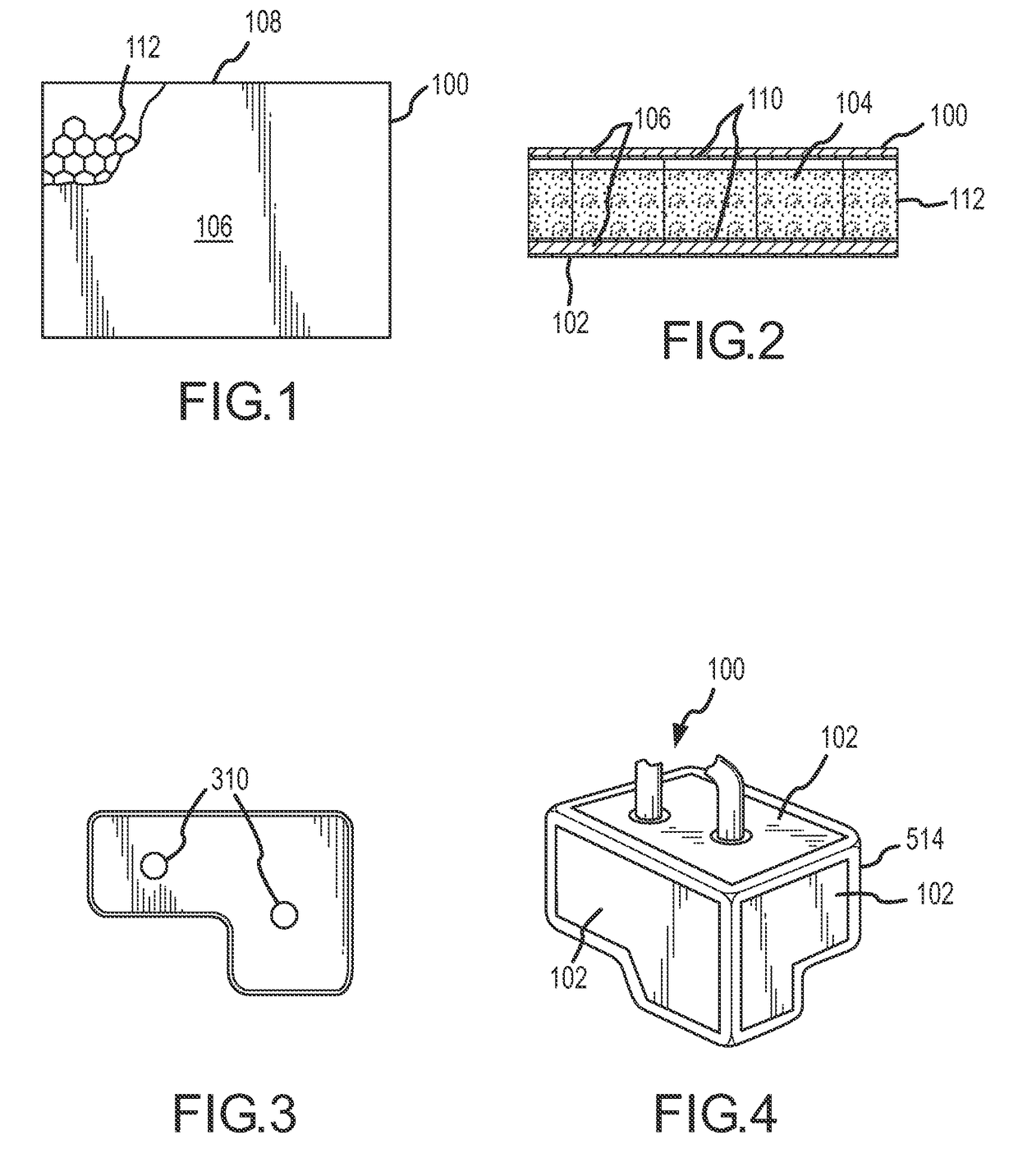
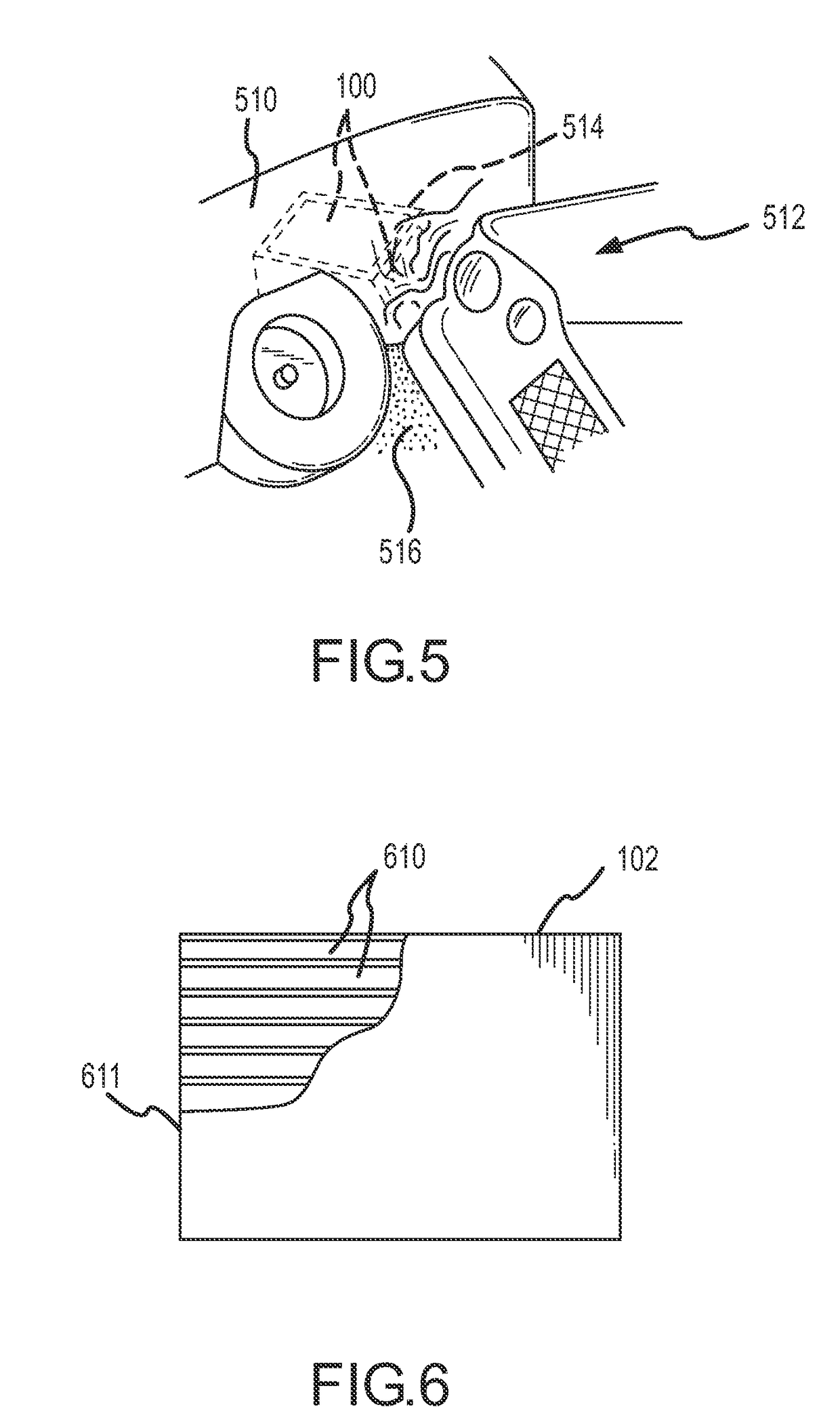
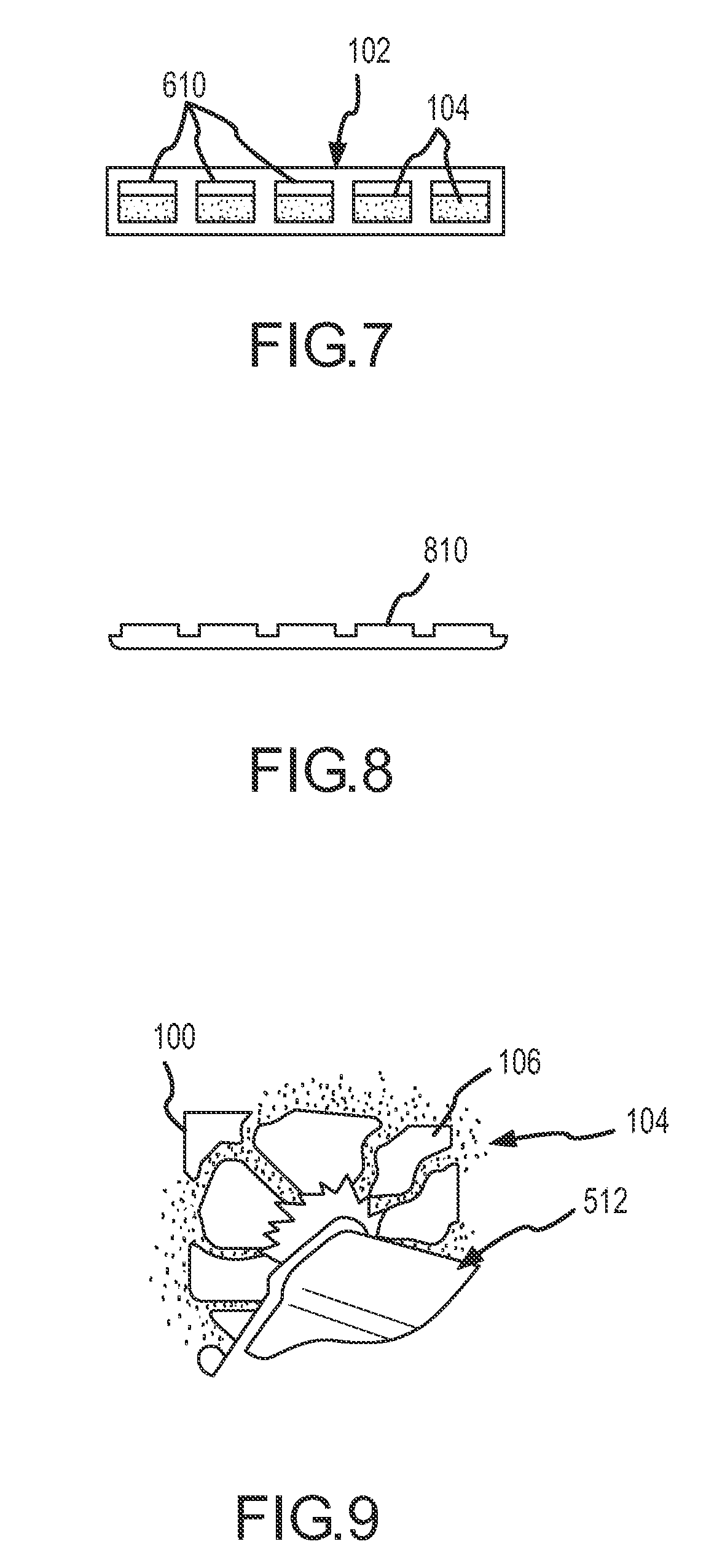
[0044]Referring now to FIGS. 1 and 2, a hazard control system 100 for controlling hazardous and / or flammable materials according to various aspects of the present invention may be implemented in conj...


PUM


Abstract

A hazard control system according to various aspects of the present invention comprises a housing configured to contain a control material and deliver the control material to neutralize a hazard in response to a trigger event. In one embodiment, the control material is an extinguishant for retarding fire. The housing contains the extinguishant and includes at least one surface configured to rupture in response to a trigger event, such as an impact. The housing may also include a surface configured to substantially mate with a surface of a vehicle, such as a fuel tank surface.

Description

CROSS-REFERENCES TO RELATED APPLICATIONS[0001]This application:[0002]is a continuation of U.S. Nonprovisional patent application Ser. No. 10 / 728,223, filed on Dec. 3, 2003 now abandoned, which[0003]claims the benefit of U.S. Provisional Patent Application No. 60 / 430,912, filed Dec. 3, 2002;[0004]is a continuation-in-part of U.S. Nonprovisional patent application Ser. No. 09 / 920,179, filed Aug. 1, 2001 now abandoned; and[0005]is a continuation-in-part of U.S. Nonprovisional patent application Ser. No. 10 / 443,302, filed May 21, 2003;[0006]and incorporates the disclosure of each application by reference.FIELD OF THE INVENTION[0007]The invention relates to methods and apparatus for controlling hazardous and / or flammable materials and the effects of such materials.BACKGROUND OF THE INVENTION[0008]Flammable and otherwise hazardous materials play an important role in the everyday lives of most people. Most people encounter flammable materials, such as gasoline, engine oil, and natural gas,...

Claims


Application Information

Patent Timeline
Patent Type & Authority Patents(United States)
IPC IPC(8): A62C2/00A62C3/00
CPCA62C3/07A62C35/02A62C35/10
Inventor BENNETT, JOSEPH MICHAEL
Owner FIRETRACE USA LLC
Learn More