Cam-lock leash

a technology of leash and cam lock, which is applied in the field of leash assembly with adjustable length leash strap, can solve the problems of user losing balance, difficulty in controlling the dog, and length of leash that can get caught in the foot of the person

Inactive Publication Date: 2011-03-22
THOMPSON SPENCER J +1
View PDF8 Cites 5 Cited by
  • Summary
  • Abstract
  • Description
  • Claims
  • Application Information

AI Technical Summary

Benefits of technology

[0007]The present invention is useful in a variety of ways. The present invention provides a pet leash that allows a person holding the leash to “reel in” their pet being held by the leash. The pet leash allows the person to “reel in” their pet by pulling on a handle that is attached to the leash strap. The present invention allows the user to adjust the length of the leash and lock the leash at a desirable length. The present invention is ergonomically designed for a pet owner's hand and allows a pet owner to use their own strength to overcome and control a pet straining against the leash.

Problems solved by technology

For example, when a dog owner is walking his or her dog on a conventional single length leash connected to a collar around the dog's neck, it can be difficult to control the dog, even though the leash is attached to the dog.
However, this is not comfortable, does not work very well, and can result in the user losing their balance as this requires the person to stoop over to grasp and then hold the animal's collar.
However, this still leaves the person holding the leash with a loose length of leash that can get caught up in the person's feet unless the person wraps or twists the leash strap about their hands or arms.
With respect to conventional single length leashes, these provide no way for the pet owner to “reel in” their pet by decreasing the length of the leash or otherwise adjust the length of the leash, without having to twist / untwist and wrap / unwrap the leash about their hands, arms, legs, and / or body.
However, these variable length designs do not allow the person to “reel” or pull in the length of the leash while the other end is attached to a pet straining against the leash in designs having a light spring powered wheel that retracts the cord or leash, but is not strong enough by itself to control and / or overcome the power of a pet, such as a dog, pulling against it.
Additionally, these retractable cord style leashes are sold with disclaimers such as “Do not use this leash for disobedient or uncontrollable dogs” and come with specific weight limitations.

Method used


Image

  • Cam-lock leash
  • Cam-lock leash
  • Cam-lock leash

Examples


Embodiment Construction

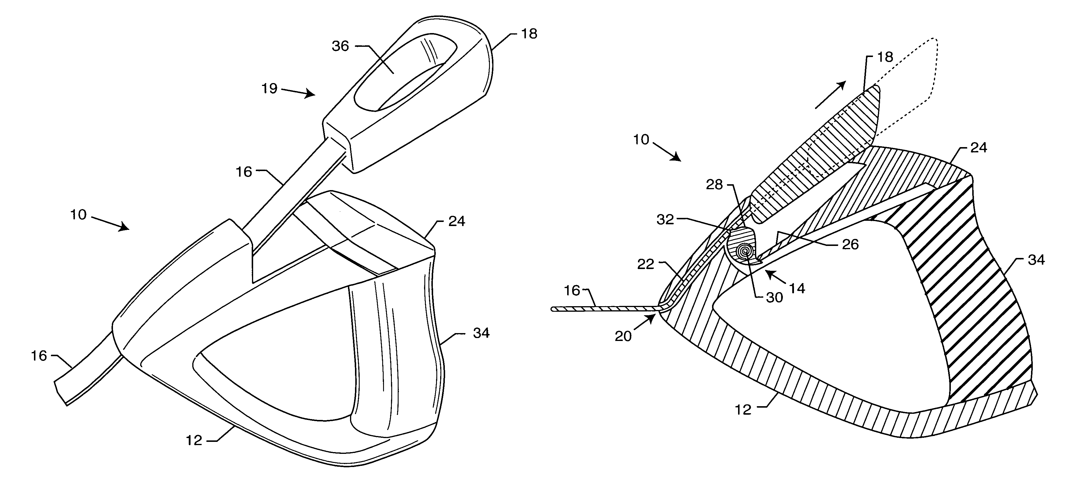
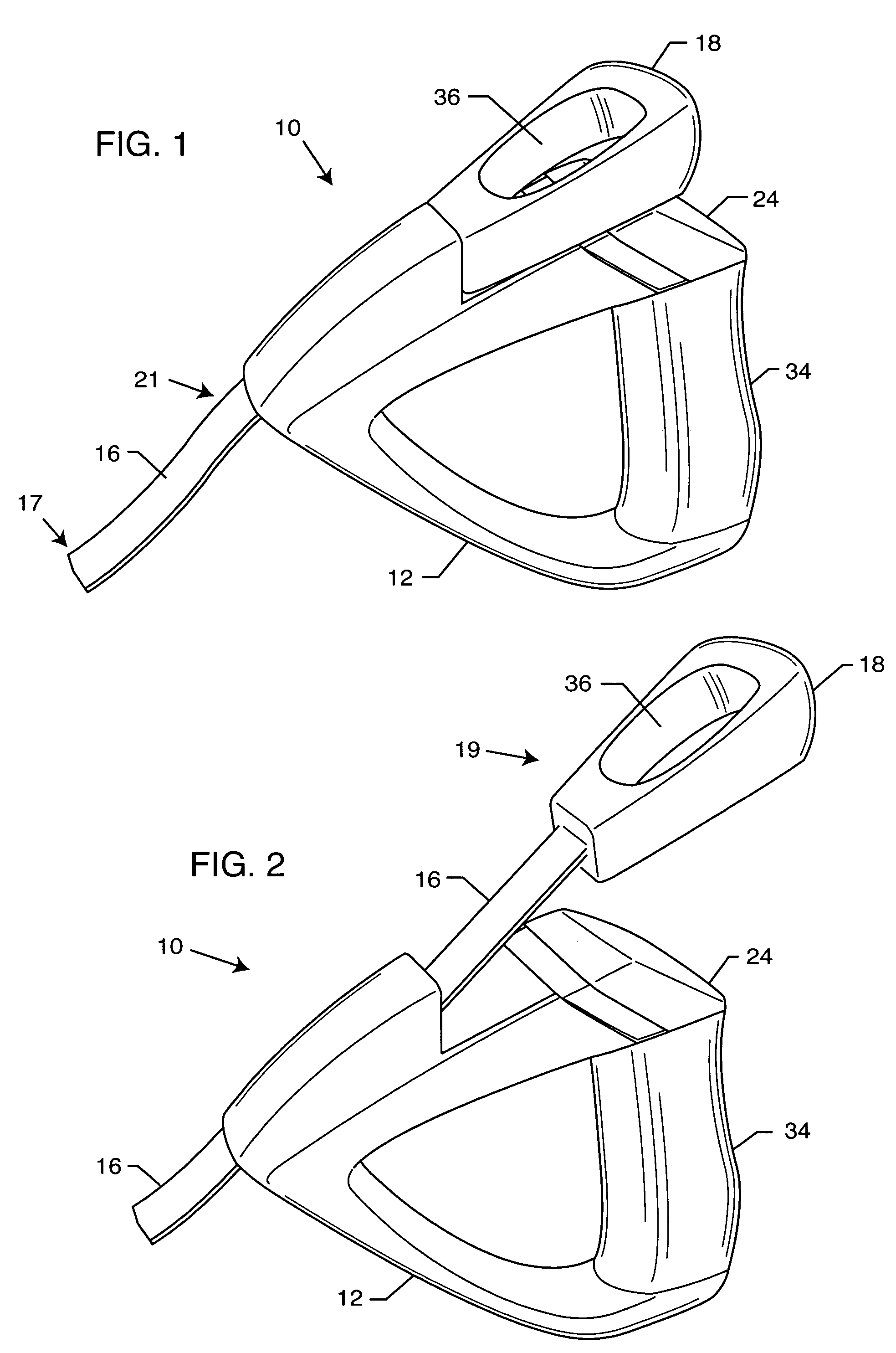
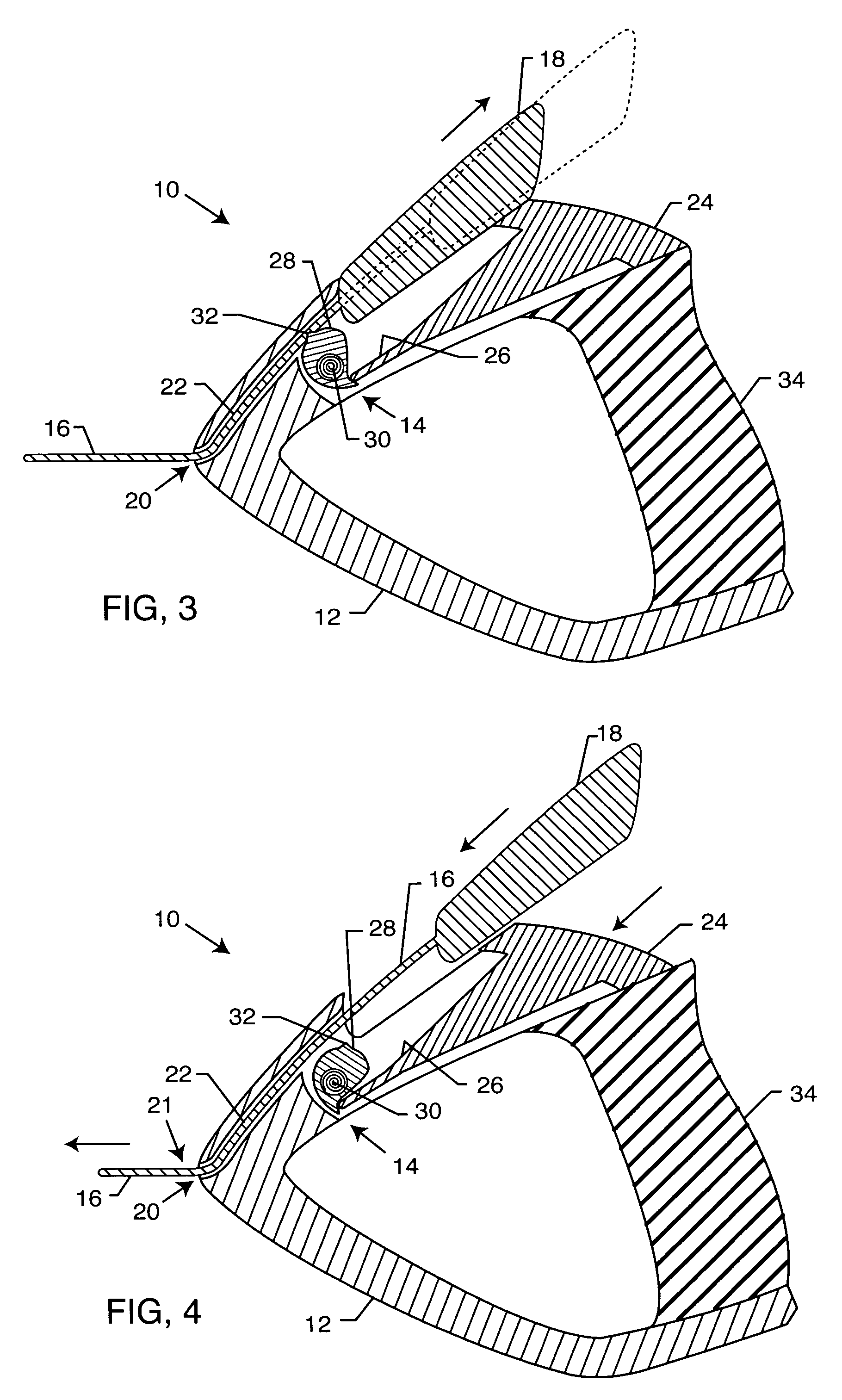
[0018]As shown in the drawings for purposes of illustration, the present invention resides in a cam-lock leash. With reference to FIGS. 1-4, a leash assembly 10 includes a housing in the form of a pistol style grip handle 12 that has an integrated cam-lock assembly 14. The assembly 10 further includes a leash strap 16 having a hook (not shown) on one end 17 that is attached to the dog's collar (not shown), and a pull-handle 18 on the other end 19, which the user grabs to pull an intermediate section 21 of the leash strap 16 through an aperture 20 of the grip handle 12, along an interior passageway in the form of a ramp or guide 22 within the handle 12 and through the cam-lock assembly 14 to shorten the length of the leash strap 16 immediately and securely. The pull-handle 18 is sized and shaped so as to engage the grip handle 12. The guide 22 enables the strap 16 to be easily pulled through the handle 12 in either direction. The cam-lock assembly 14 allows travel of the leash strap ...


PUM


Abstract

A leash assembly includes a housing having a hand grip. A leash forming part of the assembly includes a first end and a second end that defines a leash handle. An intermediate section of the leash is extendable and retractable through the housing. The assembly also includes features for allowing travel of the leash in a first direction through the housing in response to a user pulling on the leash handle, and simultaneously preventing travel of the leash in an opposite second direction through the housing. Another feature of the assembly allows selective disengagement of the leash so that it may travel in the opposite second direction through the housing.

Description

RELATED APPLICATION[0001]This application claims the benefit of U.S. Provisional Application No. 60 / 537,859, filed on Jan. 20, 2004, and entitled CAM-LOCK LEASH.BACKGROUND OF THE INVENTION[0002]The invention relates generally to a leash assembly for controlling pets. More particularly, the present invention relates to a leash assembly with an adjustable length leash strap.[0003]There is a great need for portable, efficient devices to control pets out for a walk or in any environment where a pet is not allowed to roam freely. For example, when a dog owner is walking his or her dog on a conventional single length leash connected to a collar around the dog's neck, it can be difficult to control the dog, even though the leash is attached to the dog. Typical leashes are 3 ft. to 5 ft. long and are made of a single length leash strap with a loop at one end to be gripped by the user and a connector at the other end for attachment to the collar around the dog's neck. In many situations (e.g...

Claims


Application Information

Patent Timeline
Patent Type & Authority Patents(United States)
IPC IPC(8): A01K27/00
CPCA01K27/004A01K27/005
Inventor THOMPSON, SPENCER J.EDLAUER, KEN
Owner THOMPSON SPENCER J
Why Eureka
Try Eureka