Superconductor films with improved flux pinning and reduced AC losses

a technology of superconductor films and fluxpinning, applied in the direction of superconducting magnets/coils, magnetic bodies, natural mineral layered products, etc., can solve the problems of hts tapes operating in the presence of alternating current (ac) suffering from a significant amount of energy dissipation, hts tapes and wires operating in the presence of ac, etc., to achieve simple and inexpensive, reduce ac losses, and increase flux

Inactive Publication Date: 2011-04-05
UT BATTELLE LLC
View PDF18 Cites 3 Cited by
  • Summary
  • Abstract
  • Description
  • Claims
  • Application Information

AI Technical Summary

Benefits of technology

[0014]The invention advantageously provides a simple and inexpensive method for incorporating nanoscale defects and / or filamentized features into superconducting films, which, in turn, provides superconducting films with increased flux pinning and reduced AC losses. The invention also makes possible the ability to modulate the level of AC loss reduction, flux pinning, and other attributes of the superconducting film by appropriate adjustment of the concentration of phase-separable components.

Problems solved by technology

The first HTS tapes suffered from unacceptably low critical current densities, a problem caused by poor alignment of grains in the HTS film or coating with grains of the substrate.
However, HTS tapes and wires operating in the presence of alternating current (AC) suffer from a significant amount of energy dissipation, hereinafter referred to as “AC losses”.
A major contributor to AC loss is hysteretic energy loss in the superconducting oxide film caused by an oscillating external magnetic field.
However, the techniques currently known for imparting this filamentization tend to be cumbersome, complex, and expensive.

Method used


Image

  • Superconductor films with improved flux pinning and reduced AC losses
  • Superconductor films with improved flux pinning and reduced AC losses
  • Superconductor films with improved flux pinning and reduced AC losses

Examples


example 1

Phase-Separated Layers Containing CoFe2O4 and BaTiO3 as Components Epitaxially Grown on a SrTiO3 Substrate

[0116]Phase-separated layers containing CoFe2O4 and BaTiO3 as components were grown epitaxially on a SrTiO3 substrate according to the following procedure. (100) oriented SrTiO3 substrates were mounted onto a heater of a pulsed laser ablation deposition system using silver paste. Depositions were performed using a mixed target of CoFe2O4 and BaTiO3, prepared via solid state sintering. Depositions were performed in a temperature range of 700-950° C. All depositions were performed using a KrF excimer laser (λ=248 nm). FIGS. 4a-4c are micrographs obtained using atomic force microscopy.

[0117]FIGS. 4a-4c show CoFe2O4—BaTiO3 phase-separated systems that vary in the volume concentration of the CoFe2O4 component (herein functioning as a nanophase component shown as the light-colored phase) relative to a BaTiO3 component (herein functioning as a matrix component shown as the dark-colored...

example 2

Phase-Separated Layer Containing MgO and LaMnO3 as Components Epitaxially Grown on a SrTiO3 Substrate

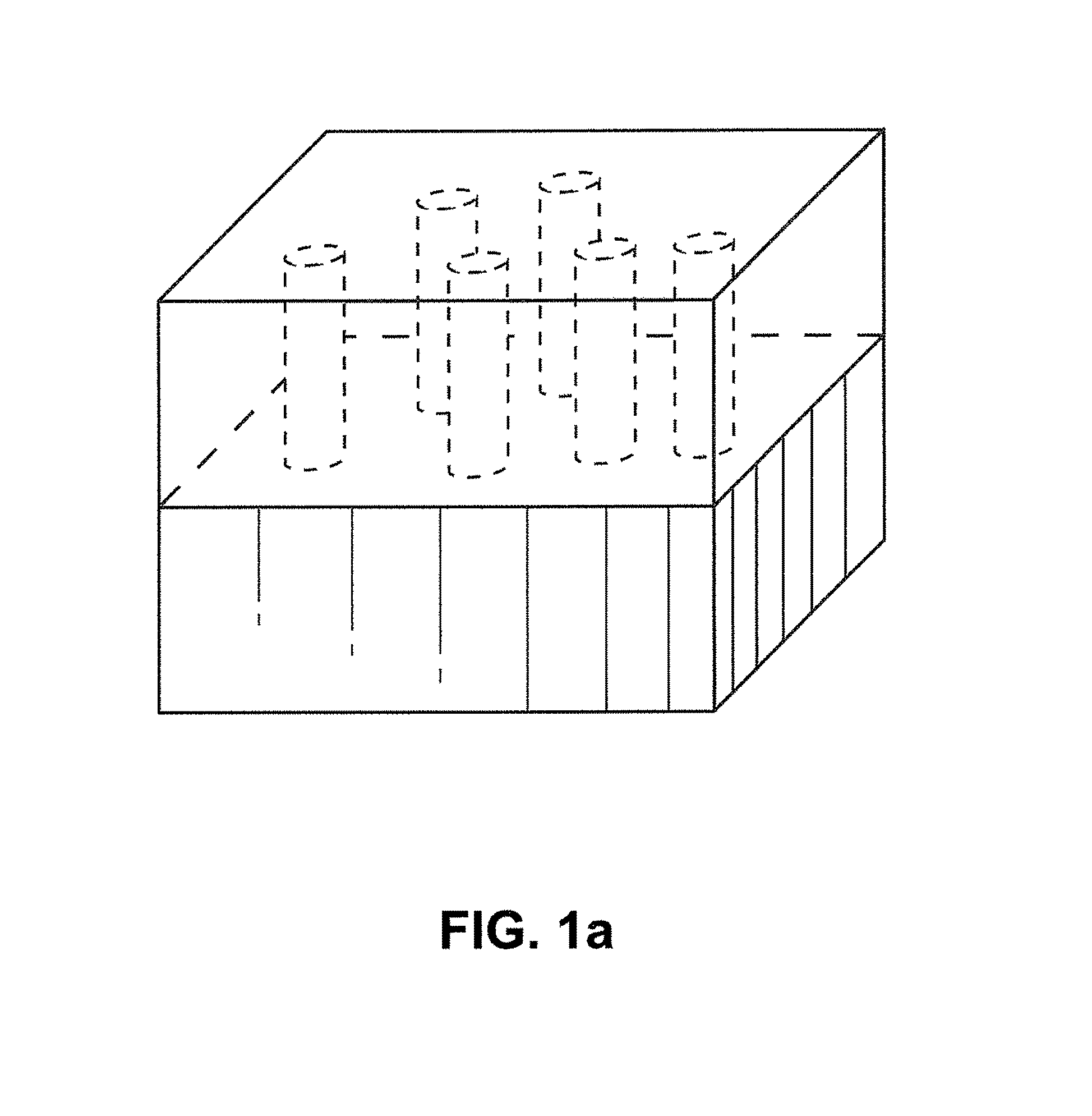
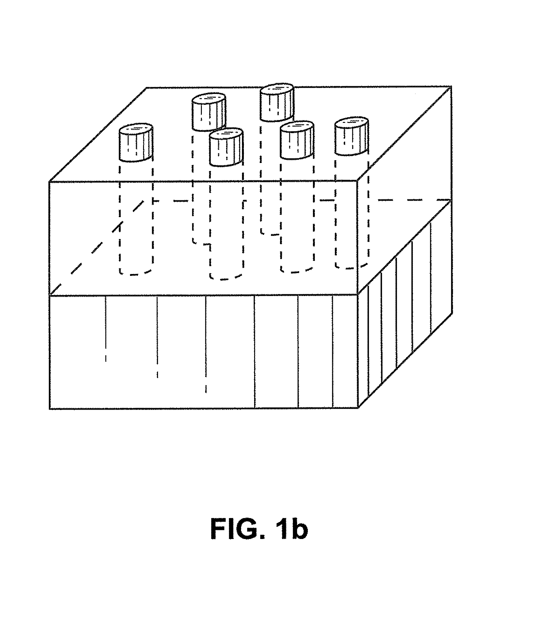
[0118]Phase-separated layers containing MgO and LaMnO3 as components were grown epitaxially on a SrTiO3 substrate according to the following procedure. (100) oriented SrTiO3 substrates were mounted onto a heater of a pulsed laser ablation deposition system using silver paste. Depositions were performed using a mixed target of MgO and LaMnO3, prepared via solid state sintering. Depositions were performed in a temperature range of 700-950° C. All depositions were performed using a KrF excimer laser (λ=248 nm).

[0119]FIG. 5a is a depiction of a phase-separated, 25 vol % MgO / 75 vol % LaMnO3 (LMO) layer of film grown epitaxially on a SrTiO3 substrate. FIG. 5b shows a theta-2theta X-ray diffraction scan of the phase-separated, 25 vol % MgO-75 vol % LaMnO3 layer of film grown epitaxially on a SrTiO3 substrate. Separate peaks corresponding to MgO and LaMnO3 can be observed indicating phase se...

example 3

Phase-Separated Layer Containing MgO and LaMnO3 as Components Epitaxially Grown on a LaMnO3 / MgO / IBAD MgO / Hastelloy® Substrate

[0120]Details of fabrication of the substrate comprised of LaMnO3 / MgO / IBAD MgO / Hastelloy® can be found in U.S. Pat. No. 6,764,770. Phase-separated layers containing MgO and LaMnO3 as components were grown epitaxially on this substrate according to the following procedure. The substrates were mounted onto a heater of a pulsed laser ablation deposition system using silver paste. Depositions were performed using a mixed target of MgO and LaMnO3, prepared via solid state sintering. Depositions were performed in a temperature range of 700-950° C. All depositions were performed using a KrF excimer laser (λ=248 nm).

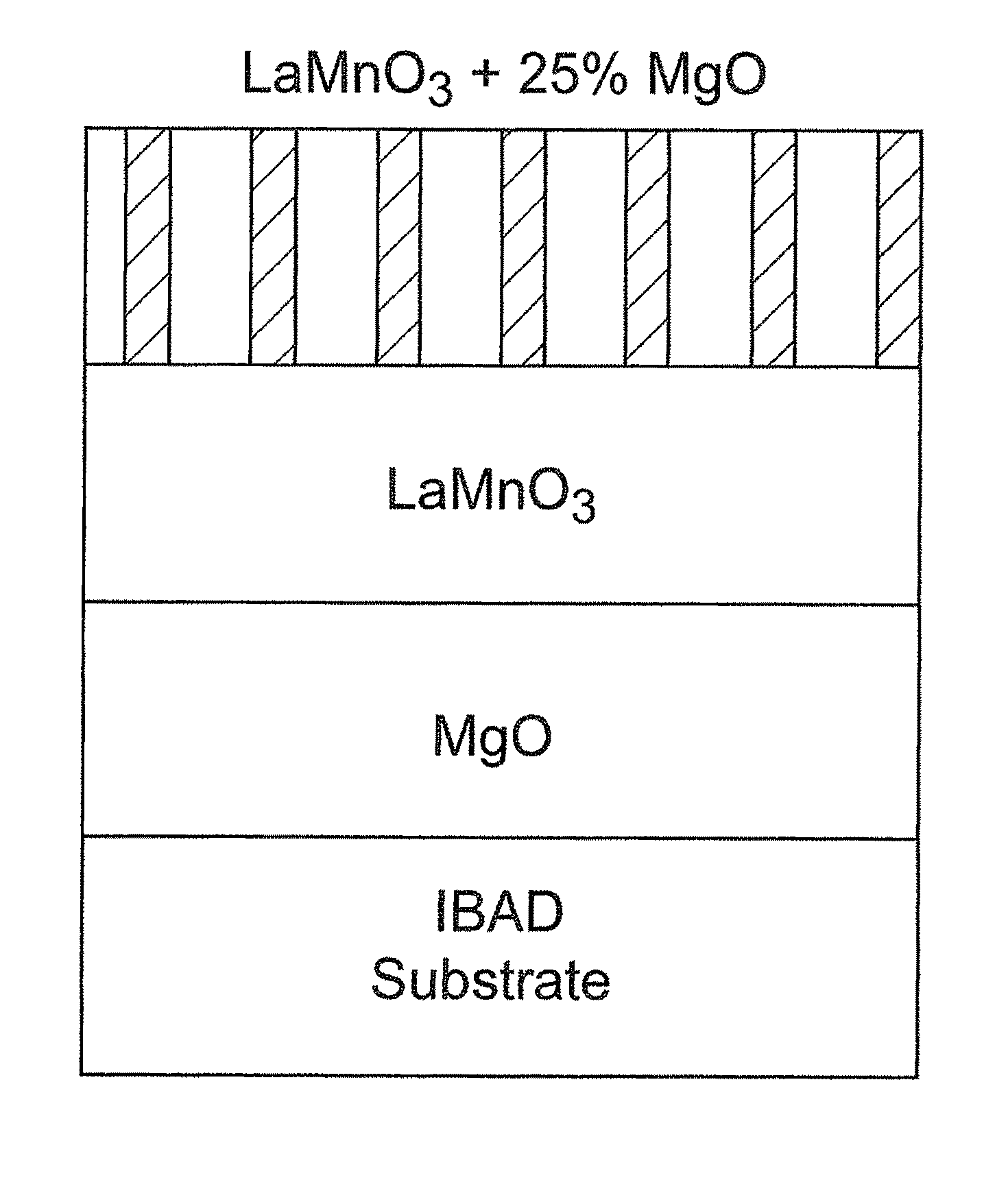
[0121]FIG. 6a is a schematic depiction of a phase-separated, 25 vol % MgO / 75 vol % LaMnO3 layer of film grown epitaxially on the LaMnO3 / MgO / IBAD MgO / Hastelloy® substrate.

[0122]FIG. 6b is a high-resolution scanning Auger map of the surface of phase-separate...


PUM

PropertyMeasurementUnit
Tcaaaaaaaaaa
Tcaaaaaaaaaa
Tcaaaaaaaaaa

Abstract

The present invention relates to a method for producing a defect-containing superconducting film, the method comprising (a) depositing a phase-separable layer epitaxially onto a biaxially-textured substrate, wherein the phase-separable layer includes at least two phase-separable components; (b) achieving nanoscale phase separation of the phase-separable layer such that a phase-separated layer including at least two phase-separated components is produced; and (c) depositing a superconducting film epitaxially onto said phase-separated components of the phase-separated layer such that nanoscale features of the phase-separated layer are propagated into the superconducting film.

Description

[0001]This invention was made with government support under Contract Number DE-AC05-00OR22725 between the United States Department of Energy and UT-Battelle, LLC. The U.S. government has certain rights in this invention.FIELD OF THE INVENTION[0002]The present invention relates to high temperature superconductor films, tapes, or wires, and more particularly, to such films, tapes, or wires with reduced AC losses and improved flux-pinning.BACKGROUND OF THE INVENTION[0003]Superconductors are capable of transmitting electricity with virtually no resistance. Accordingly, in an effort to realize significant energy savings in the use and transport of electricity, there continues to be intense interest is using superconductors in the electric power grid.[0004]All currently known superconductors require a significant degree of temperature lowering to achieve the zero-resistance state. Since the means for temperature lowering amounts to a significant expense, high temperature superconductor (H...

Claims


Application Information

Patent Timeline
Patent Type & Authority Patents(United States)
IPC IPC(8): H01L39/24H01L39/12H01B12/02H01B13/00
CPCH01L39/2461H01L39/2483Y10S505/731H10N60/0828H10N60/0632
Inventor GOYAL, AMIT
Owner UT BATTELLE LLC
Why Eureka
Try Eureka