
Periodic sensor autocalibration and emulation by varying stimulus level

a sensor and stimulus level technology, applied in the field of sensor panels, can solve problems such as difficulty in user experien

Active Publication Date: 2011-04-05
APPLE INC
View PDF26 Cites 47 Cited by
  • Summary
  • Abstract
  • Description
  • Claims
  • Application Information

AI Technical Summary

Benefits of technology

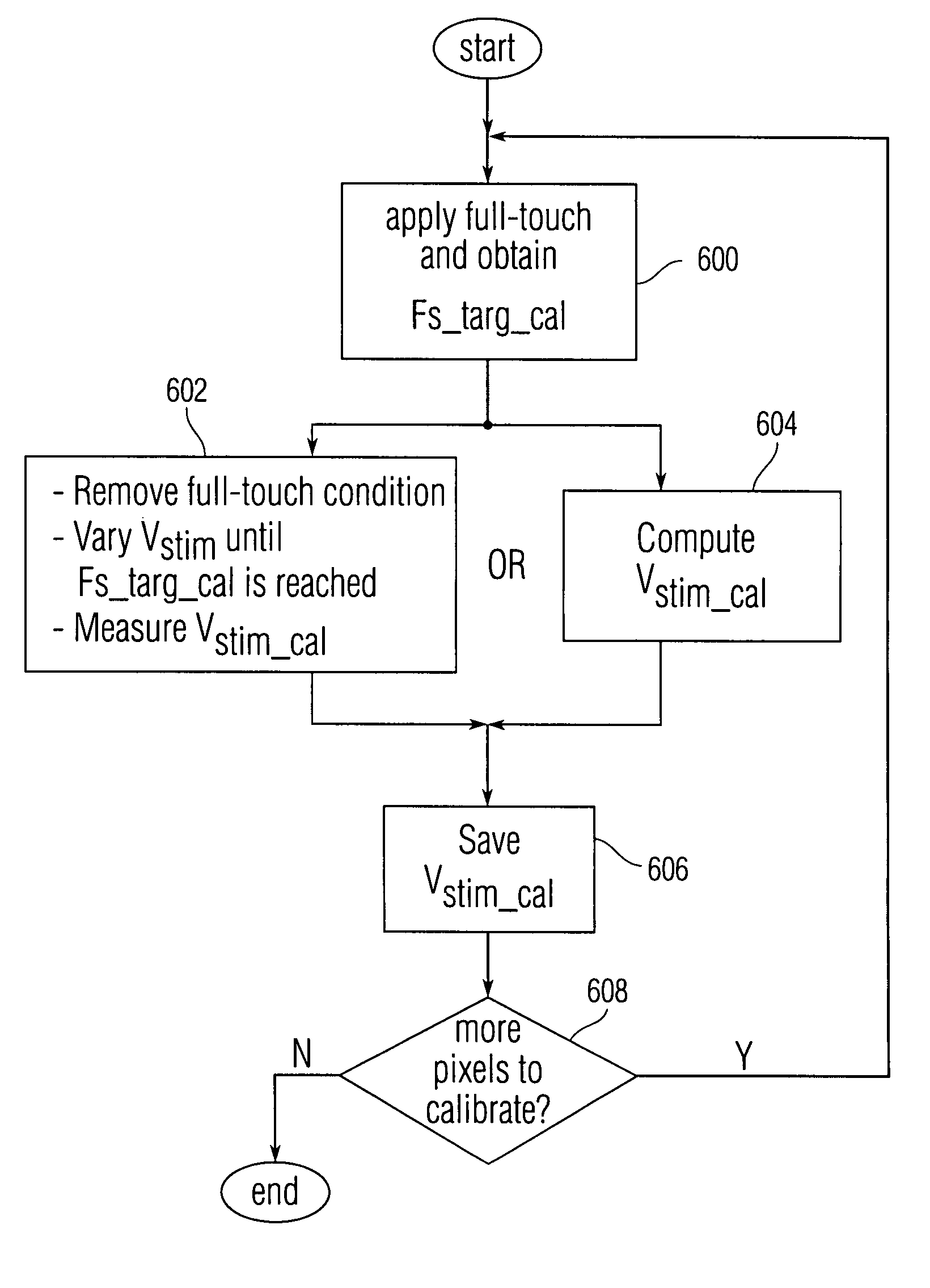
[0008]To accomplish this, a baseline full scale (i.e. full touch) ADC output (FS_targ_cal) of an analog channel can be measured before customer delivery, such as at the factory, for a particular pixel using a test fixture that can be capable of applying a no-touch to full-touch condition to each pixel in the sensor panel given a nominal Vstim amplitude. Note that this time before customer delivery can be referred to herein as “pre-delivery.” A full-touch condition can then be emulated by lowering Vstim until the ADC output for the pixel (FS_targ_current) equals FS_targ_cal. This lowered Vstim value (Vstim_cal) for each pixel can be saved for use during field calibration.

Problems solved by technology

However, because the electrical characteristics of the sensors in a sensor panel are likely to vary due to processing variations, manufacturing tolerances, assembly differences (which can be due to the location of the sensors in relation to the edges and shape of the sensor panel), aging, stress, dirt, moisture, deformation due to pressure, temperature, expansion of materials and geometries, and the like, the magnitude of the analog channel output values can vary from location to location within the sensor panel.
This can lead to inconsistent or false triggering of virtual buttons or non-triggering of virtual buttons, and a difficult user experience as the user discovers that certain areas of the sensor panel require more or less touching in order to trigger a virtual button.

Method used


Image

  • Periodic sensor autocalibration and emulation by varying stimulus level
  • Periodic sensor autocalibration and emulation by varying stimulus level
  • Periodic sensor autocalibration and emulation by varying stimulus level

Examples


Embodiment Construction

[0026]In the following description of preferred embodiments, reference is made to the accompanying drawings which form a part hereof, and in which it is shown by way of illustration specific embodiments in which the invention can be practiced. It is to be understood that other embodiments can be used and structural changes can be made without departing from the scope of the embodiments of this invention.

[0027]This relates to the automatic calibration of a sensor panel by varying the amplitude of an input stimulus to simulate a full-touch condition, and then calibrating the sensor panel in accordance with the difference between the simulated full-touch condition and a baseline full-touch condition.

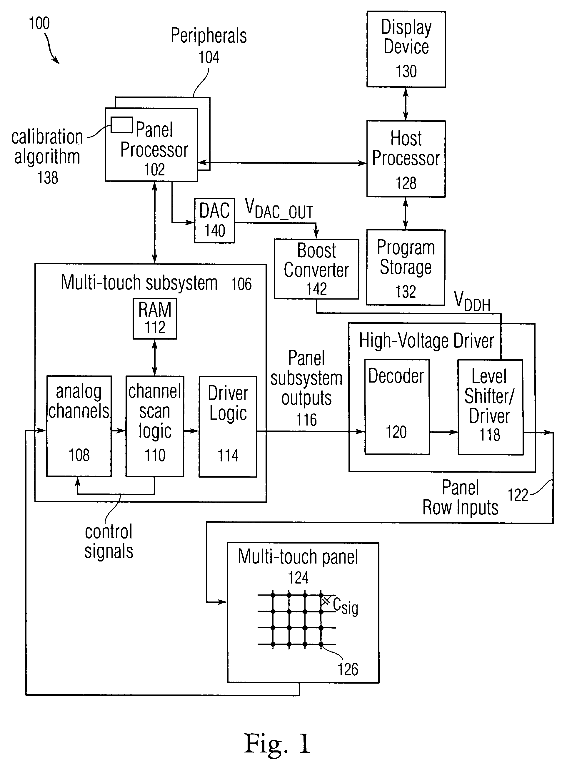
[0028]FIG. 1 illustrates exemplary computing system 100 operable with multi-touch sensor panel 124. Multi-touch sensor panel 124 can detect multiple touches (touch events or contact points) that occur at about the same time (and at different times), and computing system 100 can identify and...


PUM


Abstract

The automatic calibration of a sensor panel is disclosed by varying the amplitude of an input stimulus Vstim to simulate a full-touch condition and calibrating each pixel of the sensor panel in accordance with the difference between the simulated full-touch condition and a baseline full-touch condition. To accomplish this, a baseline full scale output FS_targ_cal can be measured at during pre-delivery calibration for each pixel using a test fixture capable of applying a no-touch to full-touch condition given a nominal Vstim. A full-touch condition can then be emulated for each pixel by lowering Vstim until the current full scale output FS_targ_current equals FS_targ_cal, and determining the Vstim value Vstim_cal at that point. During field calibration, Vstim_cal can be applied to each pixel to simulate a full-touch condition, and FS_targ_current can be obtained and compared against FS_targ_cal. Each analog channel can then be tuned so that in subsequent full-touch conditions, FS_targ_current will approximately equal FS_targ_cal.

Description

FIELD OF THE INVENTION[0001]This relates to sensor panels used as input devices for computing systems, and more particularly, to the automatic calibration of a sensor panel by varying the amplitude of an input stimulus to the sensor panel.BACKGROUND OF THE INVENTION[0002]Many types of input devices are presently available for performing operations in a computing system, such as buttons or keys, mice, trackballs, touch panels, joysticks, touch screens and the like. Touch screens, in particular, are becoming increasingly popular because of their ease and versatility of operation as well as their declining price. Touch screens can include a touch panel, which can be a clear panel with a touch-sensitive surface. The touch panel can be positioned in front of or integral with a display screen so that the touch-sensitive surface covers the viewable area of the display screen. Touch screens can allow a user to make selections and move a cursor by simply touching the display screen via a fin...

Claims


Application Information

Patent Timeline
Patent Type & Authority Patents(United States)
IPC IPC(8): G09G5/00
CPCG06F3/044G06F3/0418G06F3/0445
Inventor KRAH, CHRISTOPH HORST
Owner APPLE INC
Learn More