Cutterbar support for a crop harvesting header

a technology for harvesting headers and cutterbars, which is applied in the field of system for supporting cutterbars of crop harvesting headers, can solve the problems of unfavorable crop harvesting height, and achieve the effect of improving crop harvesting

Active Publication Date: 2011-04-26
BLUE LEAF I P INC
View PDF21 Cites 26 Cited by
  • Summary
  • Abstract
  • Description
  • Claims
  • Application Information

AI Technical Summary

Benefits of technology

[0006]An advantage of the present invention is the application of a substantially uniform support force for the cutterbar, resulting in improved crop harvesting.

Problems solved by technology

Unfortunately, the weight of cutting assembly is not uniformly distributed across the cutting width of the harvesting header, possibly causing bowing of the cutter bar, and the cutting assembly, resulting in uneven cutting height of the plant, as well as other undesirable results.

Method used


Image

  • Cutterbar support for a crop harvesting header
  • Cutterbar support for a crop harvesting header
  • Cutterbar support for a crop harvesting header

Examples


Embodiment Construction

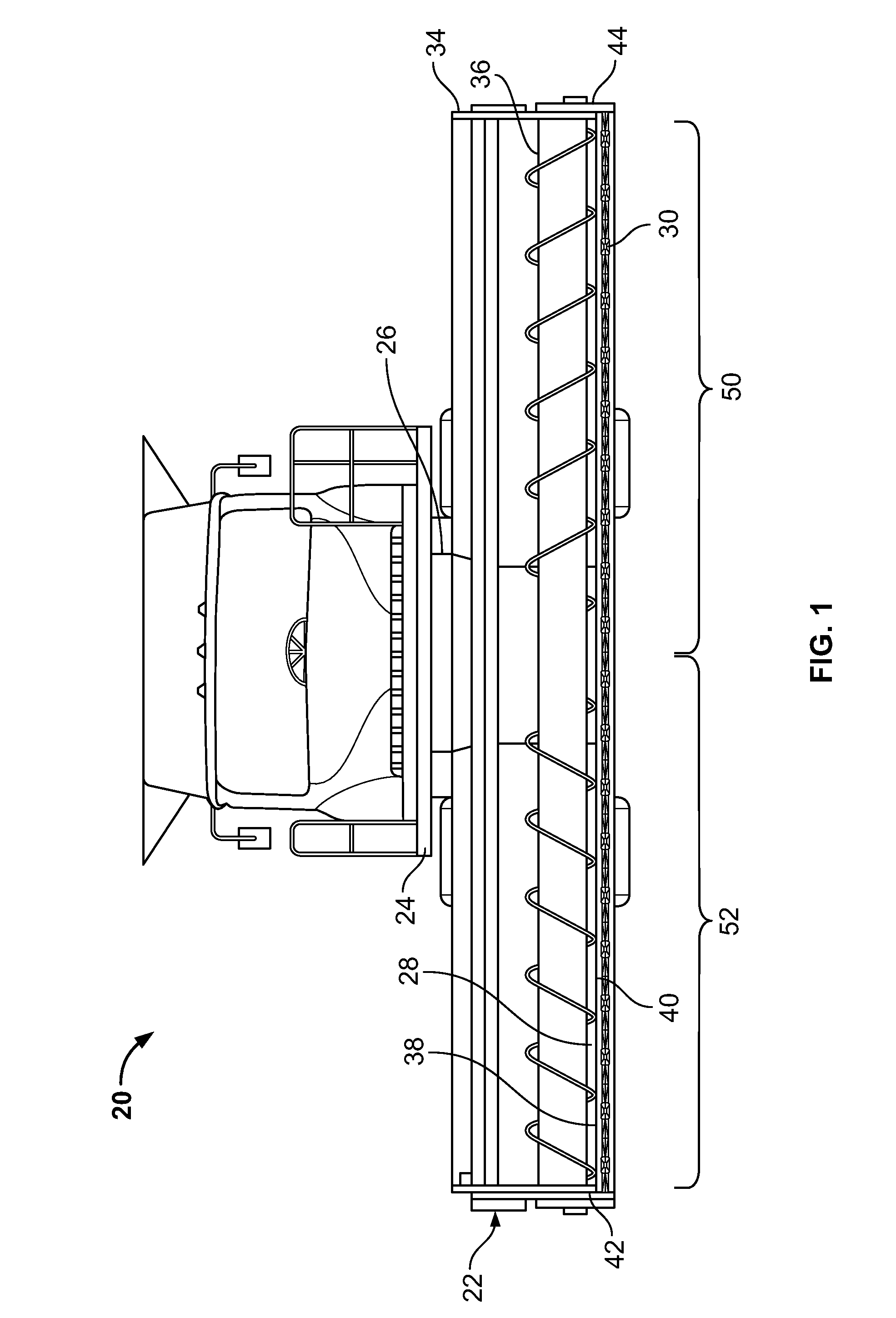
[0019]A combine 20, which is a well-known agricultural cutting and harvesting machine, is shown in FIG. 1. Combine 20 includes a header 22, which is configured to cut or sever crops, including (without limitation) small grains (e.g., wheat, soybeans), and to induct the cut or severed crops into a feeder 26. Both functions can be performed as combine 20 moves forward over a crop field.

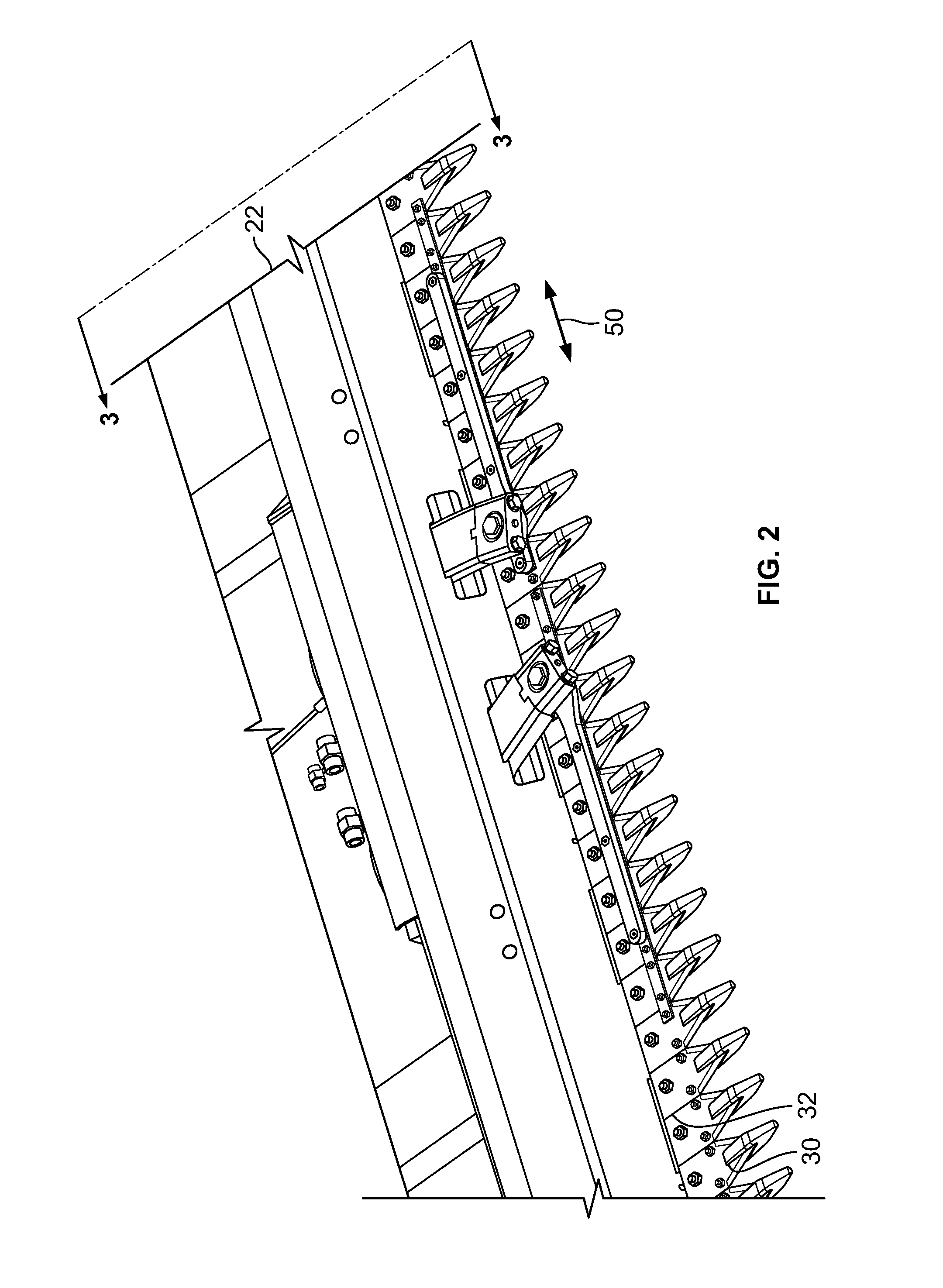
[0020]Header 22 is attached to a forward end 24 of combine 20 and includes a pan or floor 28 that is supported in desired proximity to the surface of a crop field. Header 22 includes an elongated sidewardly extending sickle 30 along a forward edge portion 32 (see FIG. 2) of floor 28. A cutter or sickle 30 is configured to cut or sever crops, in preparation for induction into a feeder 26. Additionally, header 22 may include an elongate, sidewardly extending reel 34 disposed above sickle 30. Reel 34 is rotatable in a direction suitable for facilitating the induction of cut or severed crops into feeder 26....


PUM


Abstract

A system for supporting a cutterbar of a crop harvesting header includes a first arm pivotably secured to the header and including a first portion configured to support the cutterbar, and a second portion including a torsion device connected to an adjustment assembly, the second portion configured to be pivotably rotatable about an axis by the adjustment assembly to selectably increase or decrease a force appliable to the first portion in order to raise or lower the first portion with respect to the header. The adjustment assembly includes a second arm interconnecting the torsion device and a first adjustment device having a first segment, the first adjustment device configured to movably receive a second adjustment device. The first segment follows a predetermined path in a first or second direction with respect to the axis in response to movement of the second adjustment device with respect to the first adjustment device.

Description

FIELD OF THE INVENTION[0001]The present invention relates generally to crop harvesting headers for use with crop harvesting devices. It relates more particularly to a system for supporting a cutterbar of a crop harvesting header.BACKGROUND OF THE INVENTION[0002]The cutting assemblies of the known large headers of plant-cutting machines (e.g., combine, windrower) are typically driven by an oscillating drive, which can include, but is not limited to, an eccentric shaft on a rotating hub, a wobble drive, or a similar well-known commercially-available device. A cutting assembly is typically supported by a flexible cutterbar that spans the width of the opening of the crop harvesting header. The cutterbar is typically supported by arms that extend transverse to the cutterbar. Unfortunately, the weight of cutting assembly is not uniformly distributed across the cutting width of the harvesting header, possibly causing bowing of the cutter bar, and the cutting assembly, resulting in uneven c...

Claims


Application Information

Patent Timeline
Patent Type & Authority Patents(United States)
IPC IPC(8): A01D67/00
CPCA01D41/141A01D34/283
Inventor FIGGINS, RYAN M.
Owner BLUE LEAF I P INC
Why Eureka
Try Eureka