Eureka AIR delivers breakthrough ideas for toughest innovation challenges, trusted by R&D personnel around the world.

Electrical connector

Inactive Publication Date: 2011-04-26
CHENG UEI PRECISION IND CO LTD
View PDF8 Cites 11 Cited by
  • Summary
  • Abstract
  • Description
  • Claims
  • Application Information

AI Technical Summary

Benefits of technology

[0007]As described above, the fastening piece of the shielding shell is inserted in the inserting slot of the insulating housing, and the propping portion is buckled in the locating opening, so that can avoid the shielding shell falling off from the insulating housing under an improper external force and further fasten the shielding shell to the insulating housing firmly.

Problems solved by technology

However, the shielding shell may not be firmly fastened by means of the above-mentioned assembling structure.
A deformation of the fastening piece of the shielding shell is apt to be caused by an improper external force.
As a result, the shielding shell easily falls off from the insulating housing that will affect a performance of the electrical connector.

Method used


Image

  • Electrical connector
  • Electrical connector
  • Electrical connector

Examples


Embodiment Construction

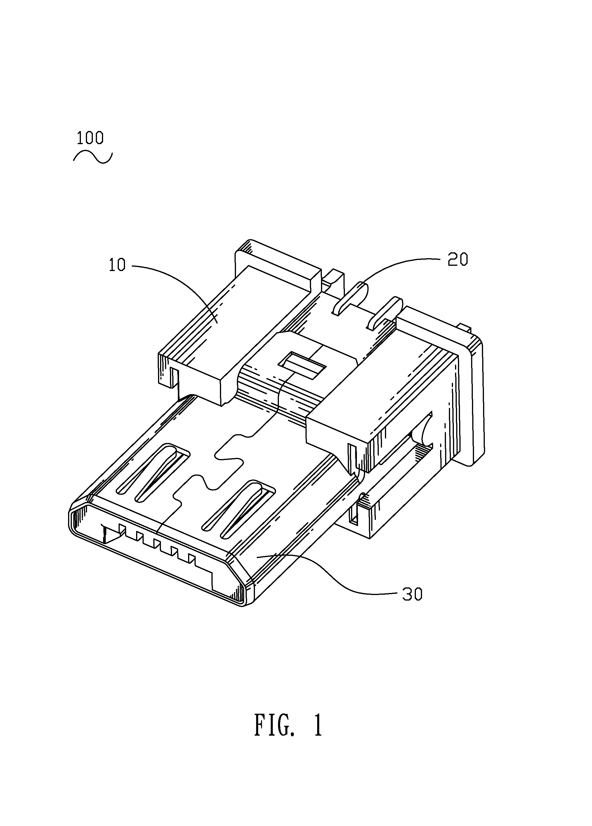
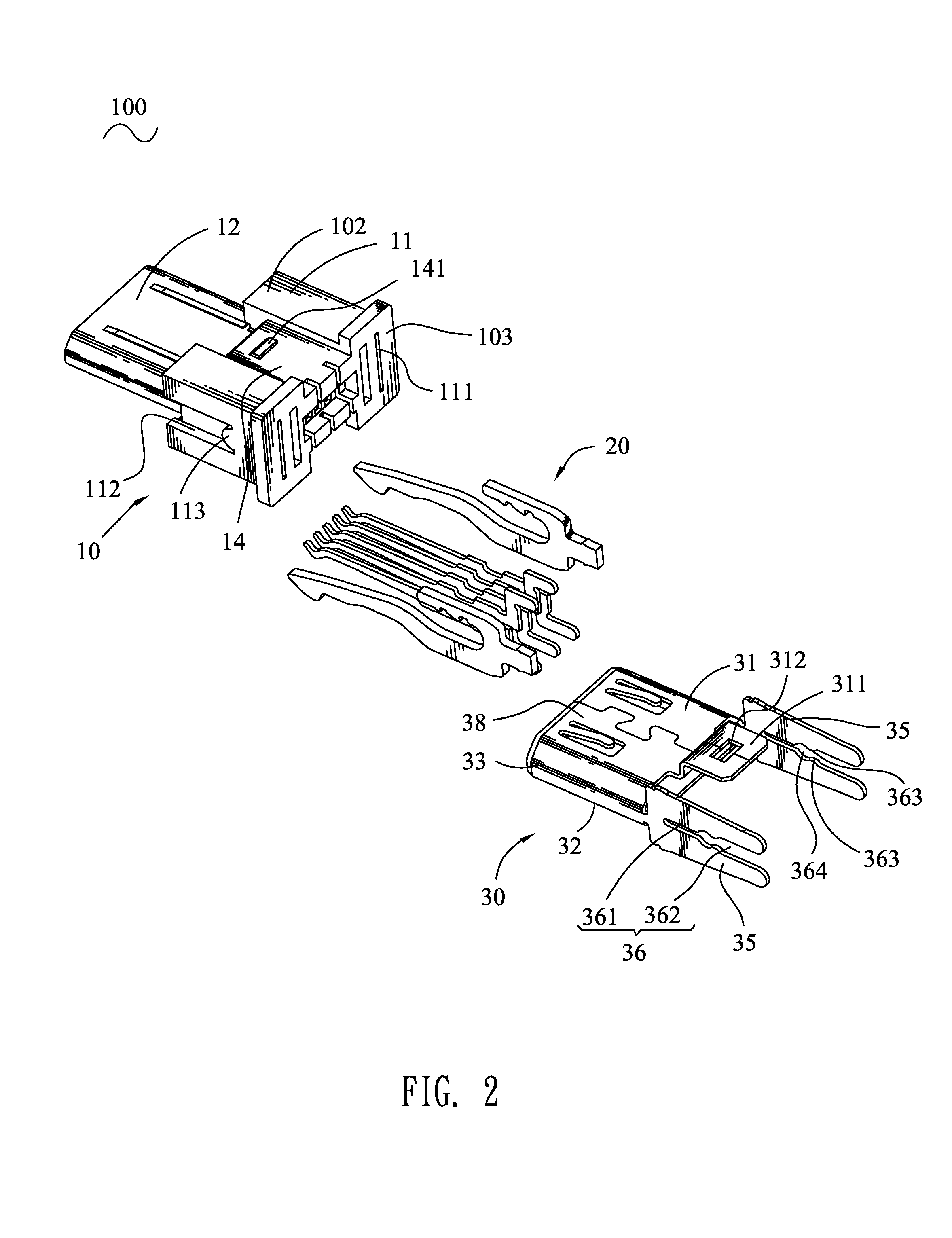
[0013]Referring to FIG. 1, an electrical connector 100 according to the present invention includes an insulating housing 10, a plurality of terminals 20 and a shielding shell 30 mounted to the insulating housing 10 respectively.

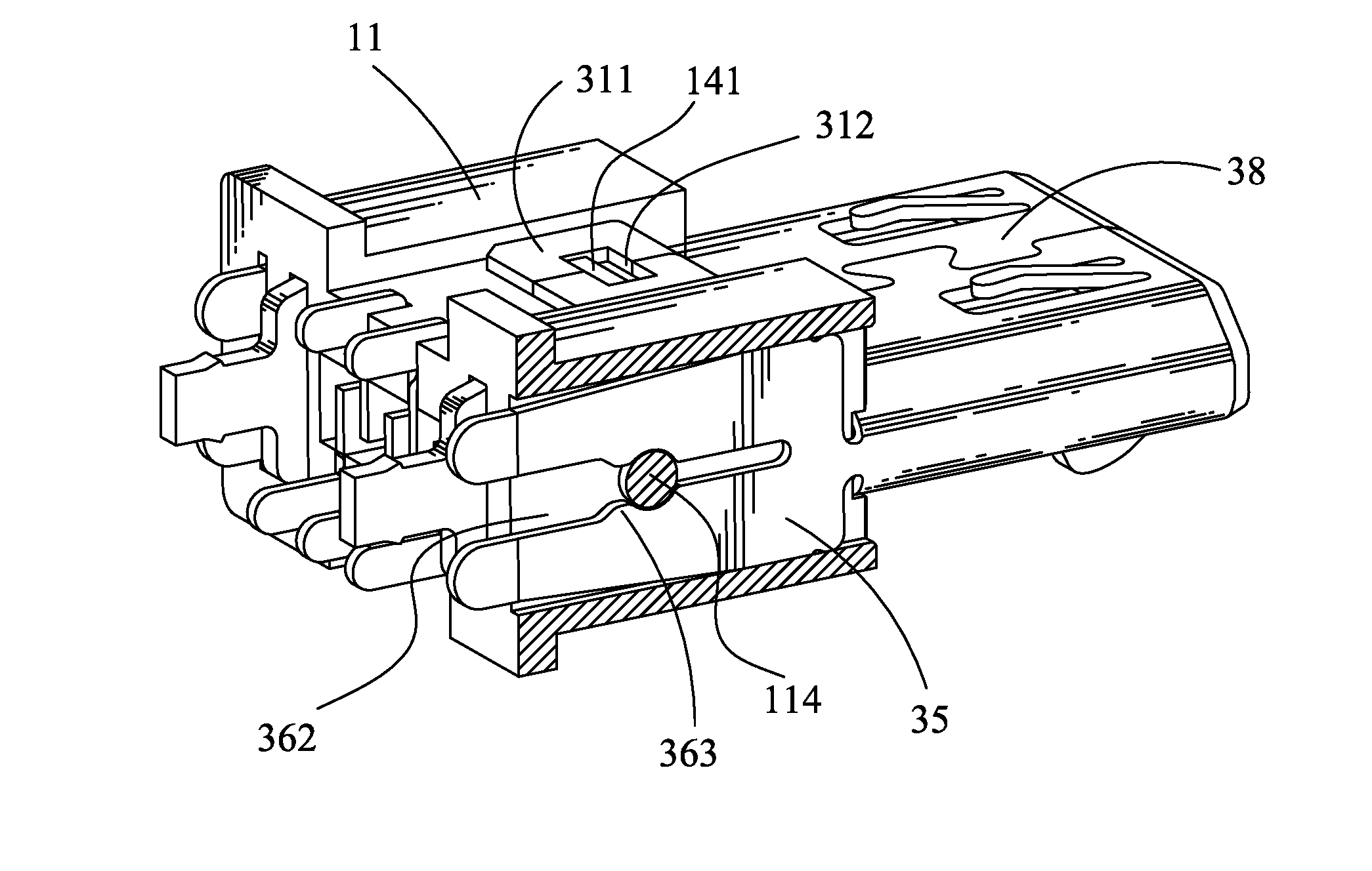
[0014]Referring to FIG. 2 and FIG. 3, the insulating housing 10 has a base body 11 of a substantially rectangular shape. The base body 11 has a front surface 101, a top surface 102 perpendicular to the front surface 101, a rear surface 103 opposite to the front surface 101 and two opposite side surfaces 104. A tongue 12 is protruded forward from a middle of the front surface 101 of the base body 11. A plurality of terminal grooves 13 are opened in a bottom of the tongue 12, and each extends longitudinally to pass through the base body 11. Two sides of the front surface 101 define two inserting slots 111 extending longitudinally to pass through the rear surface 103, and adjacent to two opposite sides of the tongue 12 and the two side surfaces 101, respectively...


PUM


Abstract

An electrical connector includes an insulating housing, a plurality of terminals and a shielding shell. The insulating housing has a base body and a tongue. Two sides of the front surface of the base body define two inserting slots. A propping portion is perpendicularly connected between two face-to-face insides of the inserting slot. The terminals are disposed in the insulating housing respectively. The shielding shell is mounted to the insulating housing, and has a tongue sheath with two side plates. A rear edge of each side plate extends rearward to form a fastening piece with a clipping opening. Two opposite edges of the clipping opening are further concaved oppositely to form a locating opening. The tongue sheath is sleeved around the tongue. The fastening piece is inserted rearward into the corresponding inserting slot, and the propping portion slides along the clipping opening until being buckled into the locating opening.

Description

BACKGROUND OF THE INVENTION[0001]1. Field of the Invention[0002]The present invention relates to an electrical connector, and more particularly to an electrical connector having a shielding shell capable of being assembled thereto tightly.[0003]2. The Related Art[0004]A traditional electrical connector generally includes an insulating housing and a shielding shell having two fastening pieces extended from two sides thereof. Conventionally, the two sides of the insulating housing are concaved inward to form two fastening grooves. The shielding shell is assembled to the insulating housing by means of fastening the fastening pieces in the corresponding fastening grooves of the insulating housing.[0005]However, the shielding shell may not be firmly fastened by means of the above-mentioned assembling structure. A deformation of the fastening piece of the shielding shell is apt to be caused by an improper external force. As a result, the shielding shell easily falls off from the insulatin...

Claims


Application Information

Patent Timeline
IPC IPC(8): H01R13/648
CPCH01R12/724H01R13/6594H01R2107/00
Inventor CHIANG, SHU-MAN
Owner CHENG UEI PRECISION IND CO LTD
Why Eureka
Eureka Blog
Learn More