
Method of assigning and deducing the location of articles detected by multiple RFID antennae

a technology of rfid reader and location, applied in the field of method, can solve the problems of increasing the range of radiated power beyond the allowable limit, affecting the operation of burglar alarm mechanical actuation, and requiring expensive and inconvenient use of such large rfid reader antenna

Active Publication Date: 2011-04-26
SENSORMATIC ELECTRONICS CORP
View PDF8 Cites 21 Cited by
  • Summary
  • Abstract
  • Description
  • Claims
  • Application Information

AI Technical Summary

Benefits of technology

[0006]In accordance with preferred embodiments of the invention, a method (and corresponding apparatus) is provided for deducing the location of one or more items or objects to be monitored. In exemplary embodiments, the method (and corresponding apparatus) is implemented in RFID (radio frequency identification) applications (e.g., reading RFID tags at 13.56 MHz and approximately 900 MHz) by deducing the location of an item associated with a unique RFID tag in one or more areas of detection covered by detectors in the form of, for example, multiple RFID reader antennae.

Problems solved by technology

However, such an antenna may be unwieldy and may increase the range of the radiated power beyond allowable limits.
Furthermore, these RFID reader antennae are often located in stores or other locations where space is at a premium and it is expensive and inconvenient to use such large RFID reader antennae.
In another possible solution, multiple small antennae may be used, but such a configuration may be awkward to set up when space is at a premium and when wiring is preferred to be hidden.

Method used


Image

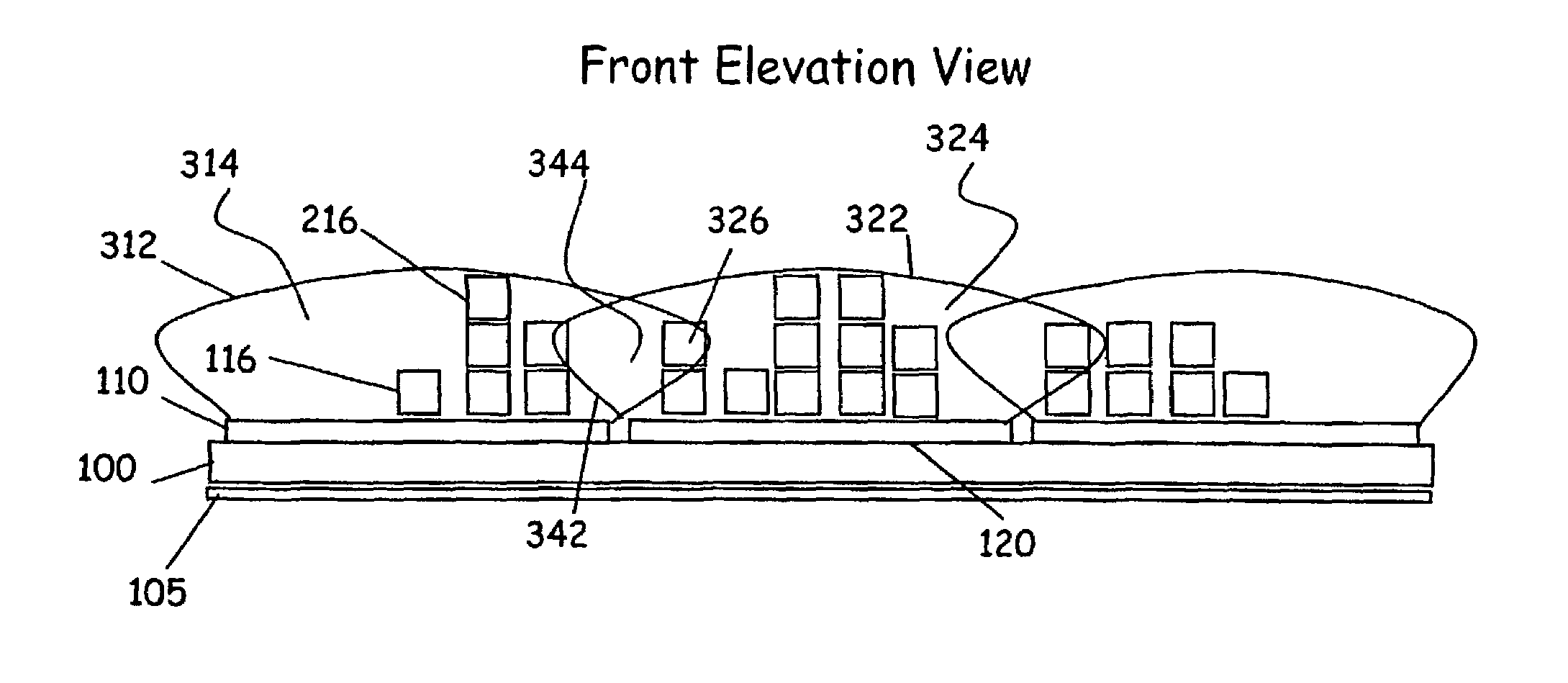
  • Method of assigning and deducing the location of articles detected by multiple RFID antennae
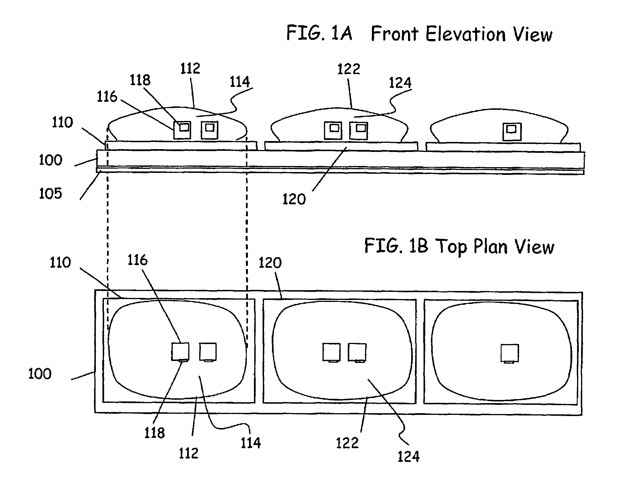
  • Method of assigning and deducing the location of articles detected by multiple RFID antennae
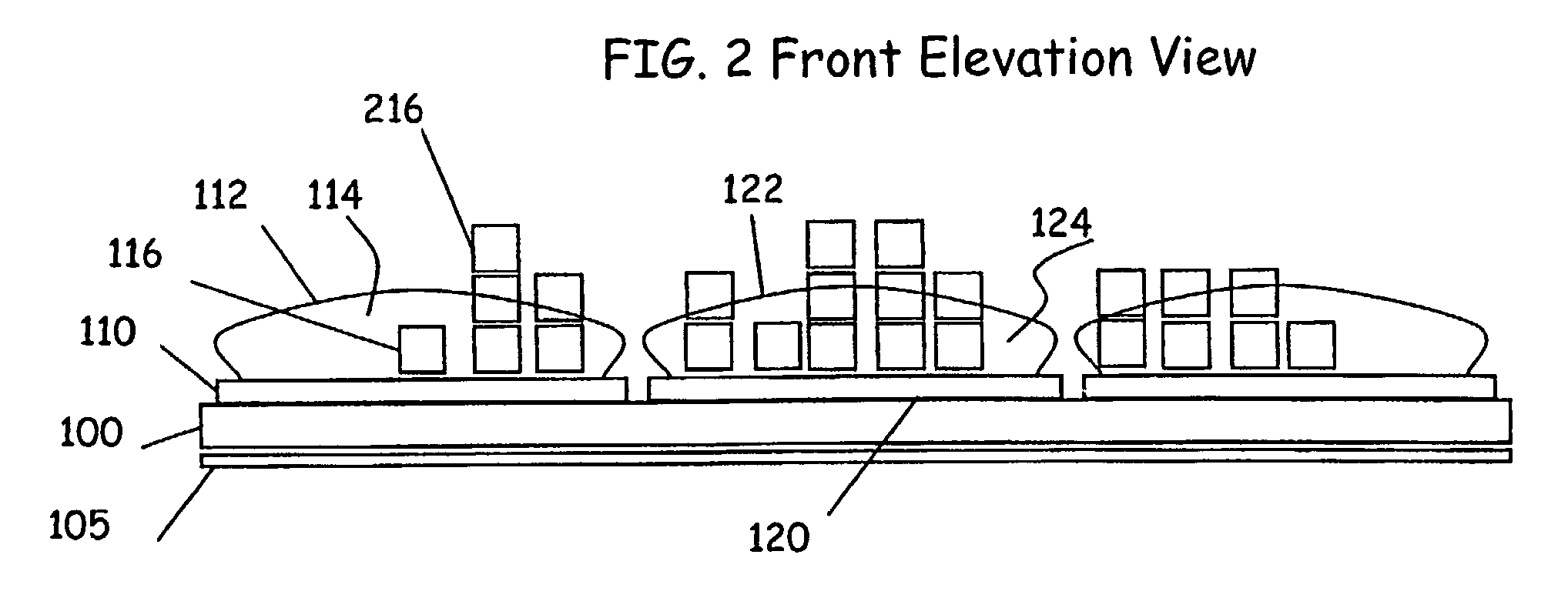
  • Method of assigning and deducing the location of articles detected by multiple RFID antennae

Examples


examples

[0088]The following are examples of specific implementations of preferred embodiments of the invention. As can be appreciated by those of ordinary skill in the art, any number of other implementations of the embodiments of the invention may be achieved when reducing embodiments of the invention to practice.

[0089]FIG. 8 shows tagged items 816, 826, and 846 such as DVD cases, each having an RFID tag such as 818, 828, and 848 respectively. The RFID tag is detected by one or more RFID reader antennae 810, 820, 830, 840 such as are disclosed in previous co pending applications. In FIG. 8, the antennae have a generally rectangular shape, and each has a feed point 835 (denoted only on antenna 830). The feed point 835 may be connected to circuitry such as tuning components, switching components, and an RFID reader (not shown here but described in previously referenced applications). The range on an RFID reader antenna such as 810 (e.g., the distance at which an RFID tag such as 818 can be r...


PUM


Abstract

In accordance with preferred embodiments of the invention, a method (and corresponding apparatus) is provided for deducing the location of one or more items or objects to be monitored. In exemplary embodiments, the method (and corresponding apparatus) is implemented in RFID (radio frequency identification) applications (e.g., reading RFID tags at 13.56 MHz and approximately 900 MHz) by deducing the location of an item associated with a unique RFID tag in one or more areas of detection covered by multiple RFID reader antennae.

Description

[0001]This application claims the benefit of U.S. Provisional Patent Application No. 60 / 568,847 ('847 application), filed May 7, 2004, and is a continuation-in-part of U.S. patent application Ser. No. 10 / 338,892 ('892 application), filed Jan. 9, 2003, now U.S. Pat. No. 7,084,769, and U.S. patent application Ser. No. 10 / 348,941 ('941 application), filed Jan. 23, 2003, where the '892 application claims the benefit of U.S. Provisional Application Nos. 60 / 346,388 ('388 application), filed Jan. 9, 2002, and 60 / 350,023 ('023 application), filed Jan. 23, 2002, where the '941 application is a continuation-in-part of the '892 application and claims the benefit of the '023 application, and where this application is related to U.S. Provisional Application Nos. 60 / 469,024 ('024 application), filed May 9, 2003, 60 / 479,158 ('158 application), filed Jun. 18, 2003, 60 / 679,846 ('846 application), filed Jun. 20, 2003, and 60 / 489,934 ('934 application), filed Jul. 25, 2003. The disclosure of each of t...

Claims


Application Information

Patent Timeline
Patent Type & Authority Patents(United States)
IPC IPC(8): G08B13/14G01S19/42G01S13/82G08B5/22
CPCG01S13/82G06K7/0008G06K17/0012G06K7/10316G06K2017/0051
Inventor CAMPERO, RICHARD J.BAUER, DONALD G.RASBAND, PAUL B.SPEDDEN, RICHARD H.JONES, MATTHEW A.
Owner SENSORMATIC ELECTRONICS CORP
Learn More