
Methods and devices for encoding a digital image signal and associated decoding methods and devices

a digital image and signal technology, applied in the field of methods and devices for encoding digital images, can solve the problems of reducing the cost of buffers, reducing and requiring a relatively high memory capacity for encoding and decoding digital images, so as to reduce the size of buffer memory needed, avoid overflow of buffer memory, and reduce implementation costs

Inactive Publication Date: 2011-05-03
CANON KK
View PDF22 Cites 10 Cited by
  • Summary
  • Abstract
  • Description
  • Claims
  • Application Information

AI Technical Summary

Benefits of technology

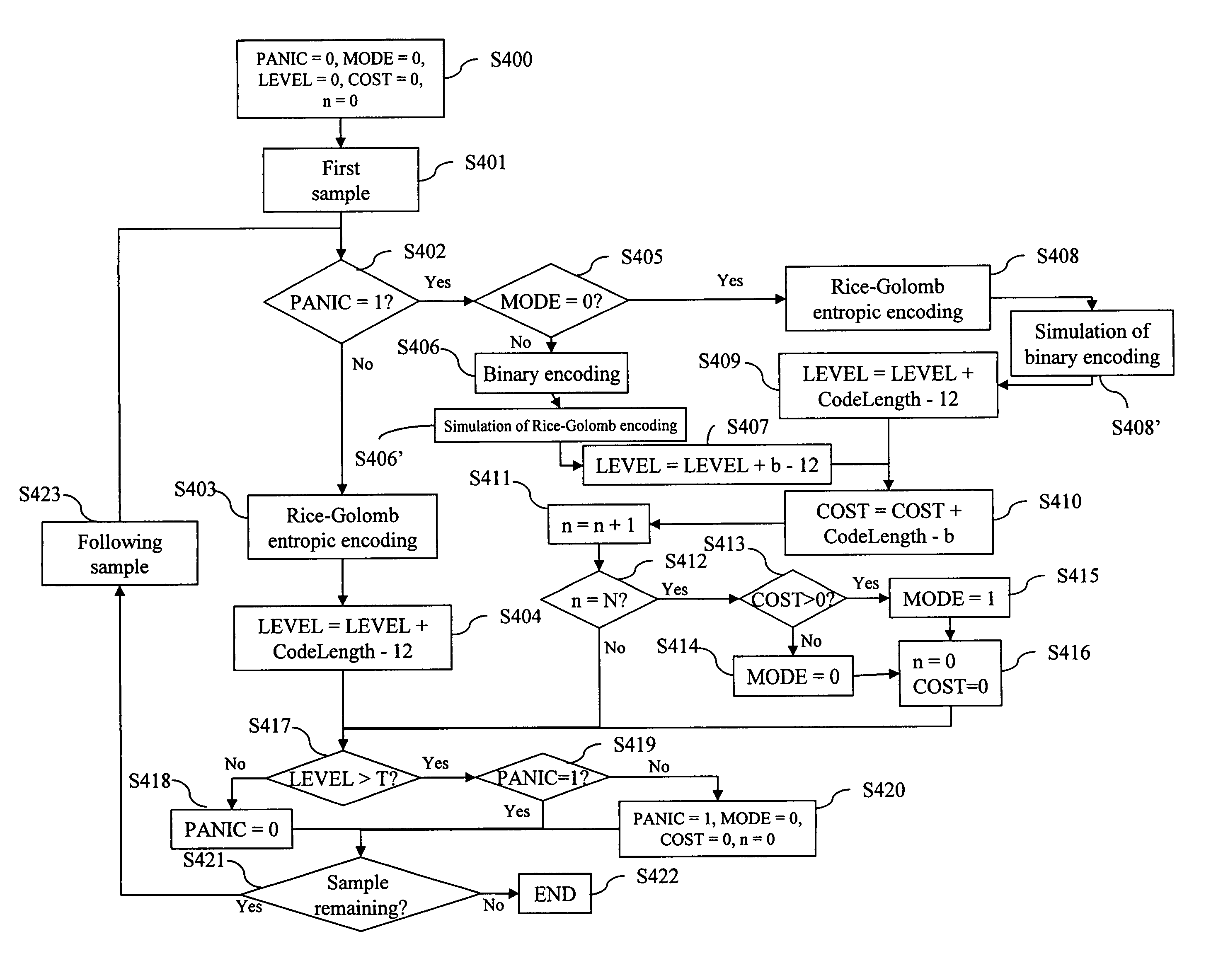
The present invention provides a method for encoding a digital image signal using a plurality of samples. The method includes steps of determining the level of occupancy of the buffer, comparing the level of occupancy with a predetermined threshold, and selecting an encoding mode based on the threshold. The method can reduce the size of the buffer and the hardware implementation cost, while also maintaining the efficiency of the encoding process. The method can be used in a continuous stream system without interrupting the sending of data. Additionally, the method allows for the evaluation of the encoding costs associated with different encoding modes to determine the best encoding mode for reducing the level of occupancy of the buffer. The method can also associate an item of information with the sample or samples to indicate the encoding mode used.

Problems solved by technology

It is known that the operations of encoding and decoding digital images require a relatively high memory capacity as well as a long processing time.
Moreover, the size of the data output by these operations may be relatively high, which has a direct impact on the capacity of the buffer or buffers necessary for storing these data.
However, the cost of buffers is generally higher, the greater the storage capacity.
Moreover, It is known that, when a signal encoding technique (for example, the encoding of images) is implemented in practice, the problem of the difference in the rate of input of the data of the signal in the encoding device and the rate of output from the encoding device must be managed.
The variable output rate of the encoding device may cause the generation of a quantity of data that is too great with respect to the capabilities of processing of the system which follows the encoding device.
Moreover, the size of the data coming from the encoding device may be relatively high, which has a direct impact on the capacity of the buffer memory necessary for the storage of those data.
However, the cost of the buffer memories is generally all the higher that the storage capacity is great.
However, the smaller the size of the buffer memory, the greater the risk during the encoding of images of the buffer memory being full, which then causes the process to stop.
For example, if it is an encoding device installed in a digital apparatus, it must be ensured that the size of the buffer memory is such that the problem is never encountered during the term of use of that apparatus.
However, this method has the drawback of effecting an encoding with loss, which is not always acceptable.
However, such data must nevertheless be held in memory in order to be combined, so necessitating memories of relatively large sizes.
However, these methods have the drawback not only of using buffer memories of which the size is relatively great without however ensuring avoidance of the size of the buffer memory being exceeded, but also, of having low flexibility with respect to a strong unexpected increase in the use of the buffer memory.
Furthermore, according to these methods, the large majority of the capacity of the buffer memory is never used.

Method used


Image

  • Methods and devices for encoding a digital image signal and associated decoding methods and devices
  • Methods and devices for encoding a digital image signal and associated decoding methods and devices
  • Methods and devices for encoding a digital image signal and associated decoding methods and devices

Examples


Embodiment Construction

[0149]The encoding / decoding methods and devices according to the invention are now described in the context of their application to the processing of multimedia entities in the form of digital images.

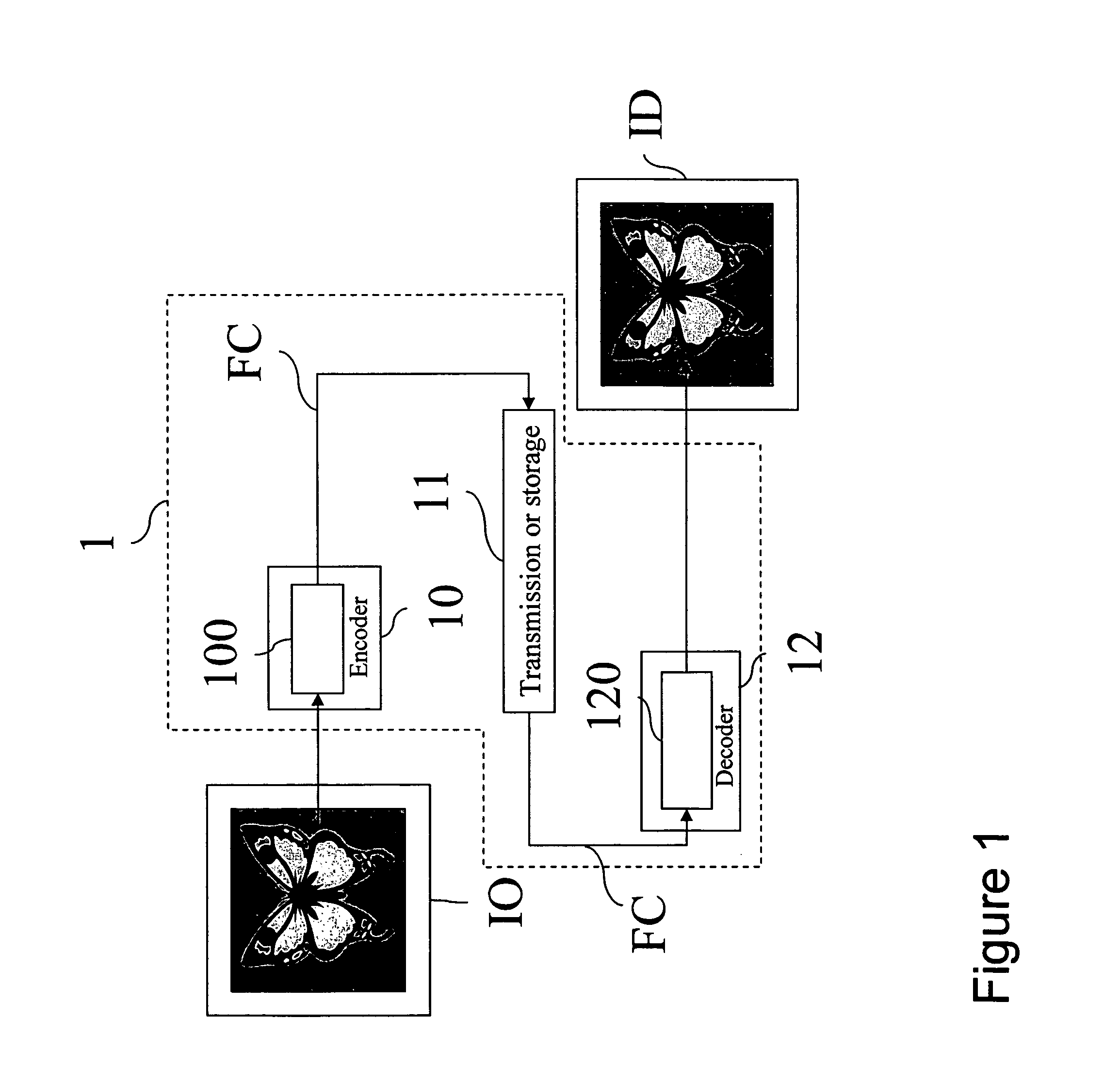
[0150]With reference to FIG. 1 and designated by the general reference 1, a system for processing digital images incorporating encoding / decoding processing without loss according to the invention uses an encoder 10, a unit 11 and a decoder 12.

[0151]It should be noted here that the encoding / decoding methods according to the invention provide a particularly advantageous application in a telecommunications system comprising a plurality of terminal devices connected through a telecommunications network. The encoding / decoding methods according to the invention are then used in the terminal devices of the system so as to enable transmission of files through the telecommunications network and thus reduce the traffic and transmission times.

[0152]According to another particularly advantageous ap...


PUM


Abstract

A method of encoding a digital image signal comprising a plurality of samples. The method comprises the following steps, applied during the encoding of each sample with a view to its storage in a buffer. The level of occupancy of the buffer is determined, and the level of occupancy is compared with a predetermined threshold. An encoding mode is determined from among a plurality of encoding modes when the level of occupancy is above the predetermined threshold, and encoding the sample according to the determined encoding mode, and the sample is encoded according to a default encoding mode when the level of occupancy is below the predetermined threshold.

Description

FIELD OF THE INVENTION[0001]The present invention concerns a method and device for encoding an image as well as a method and device for decoding an encoded image.[0002]The present invention concerns in general terms the encoding and decoding of multimedia entities that is to say digital text, voice and / or image signals, without loss of digital signals and avoiding overflow of the buffer memory.[0003]A particularly advantageous, but not exclusive, preferred application of the present invention is the encoding / decoding of digital images without loss and using a buffer memory of reduced size, for example in the field of medical imaging or digital cameras.BACKGROUND OF THE INVENTION[0004]A digital image coming for example from a digital photographic apparatus consists of a set of N×M pixels, where N is the height of the image in pixels and M the width of the image. The image thus obtained is encoded before being stored in memory. The initial data, that is to say the information represen...

Claims


Application Information

Patent Timeline
Patent Type & Authority Patents(United States)
IPC IPC(8): G06K9/46
CPCH04N19/172H04N19/152H04N19/15H04N19/13
Inventor GISQUET, CHRISTOPHEHENRY, FELIX
Owner CANON KK
Learn More