
Knife connector

a connector and blade technology, applied in the field of connectors, can solve the problems of unchangeable blade body of conventional cutting tools and inflexible us

Inactive Publication Date: 2011-05-10
CHEN KUN CHEN +1
View PDF5 Cites 6 Cited by
  • Summary
  • Abstract
  • Description
  • Claims
  • Application Information

AI Technical Summary

Problems solved by technology

However, the blade body of the conventional cutting tool is undetachably connected to the handle, so the blade body of the conventional cutting tool is unchangeable and not versatile in use.

Method used


Image

  • Knife connector
  • Knife connector
  • Knife connector

Examples


Embodiment Construction

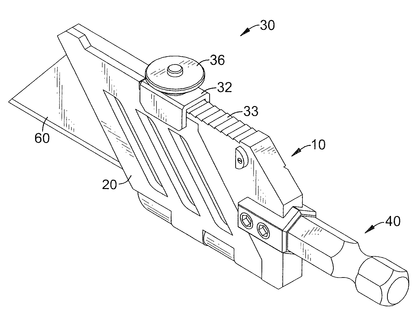
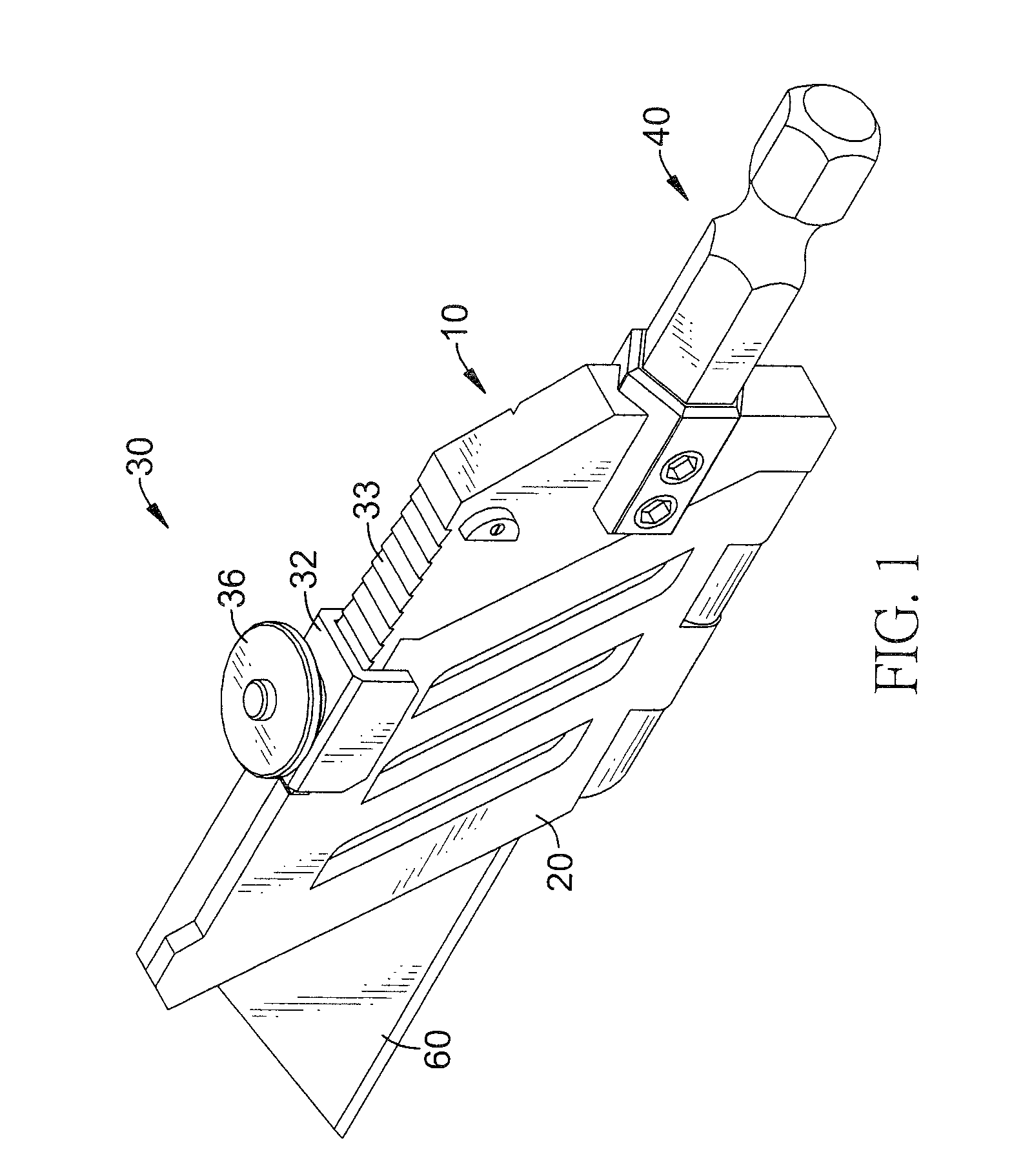
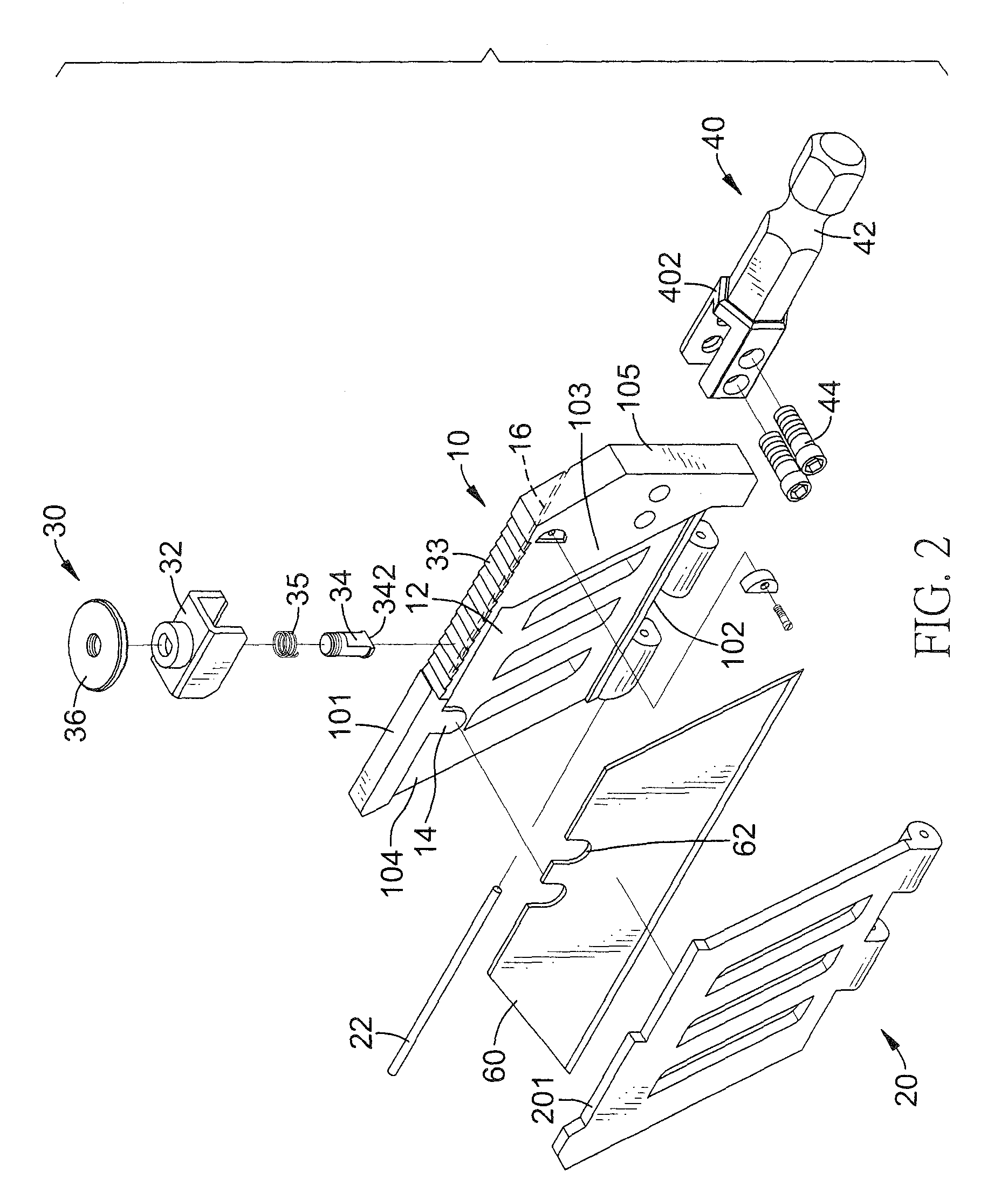
[0016]With reference to FIGS. 1 to 3, a knife connector in accordance with the present invention comprises a base (10), a cover (20), a clamping device (30) and a connecting stub (40).

[0017]The base (10) has a top edge (101), a bottom edge (102), a holding side (103), a knife-holding end (104), a connecting end (105) opposite to the knife-holding end (104) and a holding cavity (12). The holding cavity (12) is defined in the holding side (103) and has an opening defined in the knife-holding end (104).

[0018]In addition, the base (10) further has a positioning device mounted on the holding side (103) to position one end of a blade body (60) in the holding cavity (12). In an embodiment, the positioning device comprises a protrusion (14) formed on a top edge of the holding cavity (12) and engaging one of notches (62) in a blade body (60) as shown in FIG. 2. In an alternative embodiment, the positioning device comprises a knob (15) formed on a bottom of the holding cavity (12) and mounted...


PUM

PropertyMeasurementUnit
forceaaaaaaaaaa
lengthaaaaaaaaaa
shapeaaaaaaaaaa

Abstract

A knife connector includes a base, a cover, a clamping device and a connecting stub. The base has a holding side, a knife-holding end, a connecting end opposite to the knife-holding end and a holding cavity. The holding cavity is defined in the holding side and has an opening defined in the knife-holding end. The cover is pivotally connected to the base to close the holding cavity. The clamping device is mounted on the base and holding the cover on the base to close the holding cavity. The connecting stub is mounted on the connecting end of the base and has a non-circular cross section and an engaging recess defined around the connecting stub. Accordingly, the knife connector can detachably and changeably connect a blade body to a handle to fit with different kinds of cutting tools.

Description

BACKGROUND OF THE INVENTION[0001]1. Field of the Invention[0002]The present invention relates to a connector, and more particularly to a connector for holding a knife, a blade, a saw or the like and detachably and changeably connecting the knife to a handle.[0003]2. Description of Related Art[0004]A conventional cutting tool, such as a knife, blade or a saw substantially comprises a handle and a blade body securely attached to the handle, such that a user can cut an object with the cutting tool. However, the blade body of the conventional cutting tool is undetachably connected to the handle, so the blade body of the conventional cutting tool is unchangeable and not versatile in use.[0005]To overcome the shortcomings, the present invention tends to provide a knife connector to mitigate or obviate the aforementioned problems.SUMMARY OF THE INVENTION[0006]The main objective of the invention is to provide a knife connector that can detachably and changeably connect a blade body to a han...

Claims


Application Information

Patent Timeline
Patent Type & Authority Patents(United States)
IPC IPC(8): B26B5/00
CPCB23D51/10B27B21/04B26B5/00Y10T83/9481
Inventor CHEN, KUN-CHEN
Owner CHEN KUN CHEN
Learn More