Belt rib wear gauge

a belt rib and wear gauge technology, applied in the direction of instruments, mechanical measuring arrangements, roads, etc., can solve the problems of belt ribs adjacent to the groove, wear and the size of belt ribs, and the performance problem of the accessory belt drive system

Inactive Publication Date: 2011-05-24
THE GATES CORP
View PDF16 Cites 15 Cited by
  • Summary
  • Abstract
  • Description
  • Claims
  • Application Information

AI Technical Summary

Problems solved by technology

Such wear is difficult to visually diagnose and can lead to performance problems in the accessory belt drive system, for example, slipping and noise.
Belt wear in multi-ribbed belts manifests as an increase in belt groove width and depth, which results from wear and reduction in size of the belt ribs adjacent to the groove.

Method used


Image

  • Belt rib wear gauge
  • Belt rib wear gauge
  • Belt rib wear gauge

Examples


Embodiment Construction

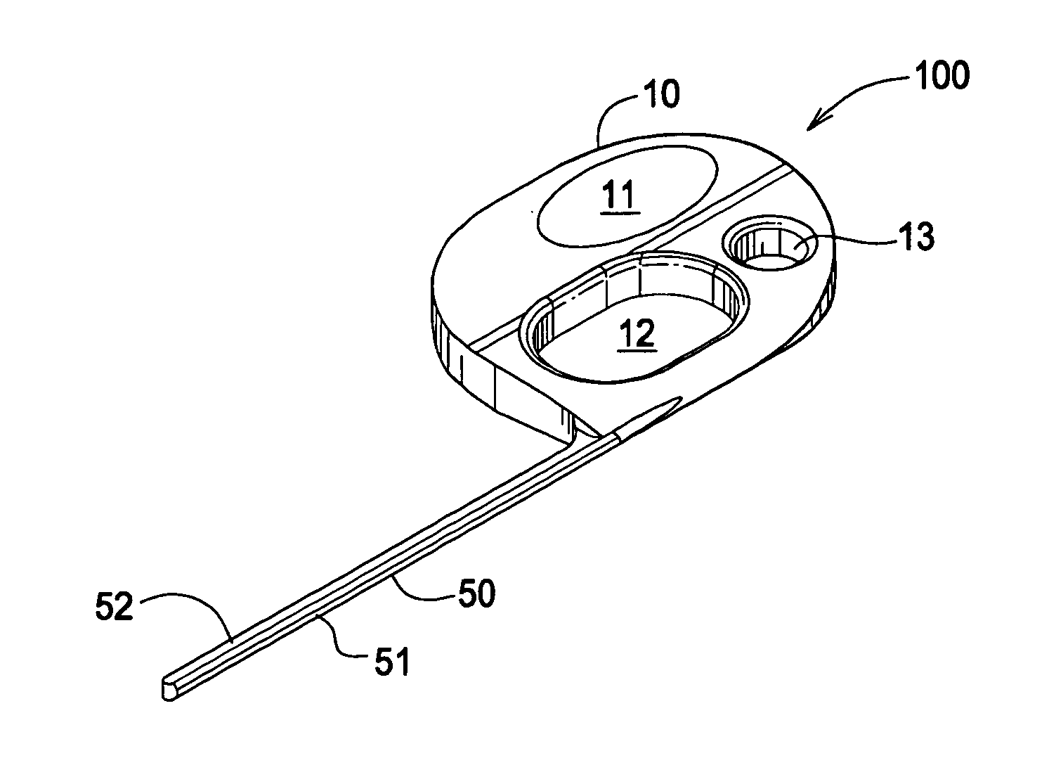
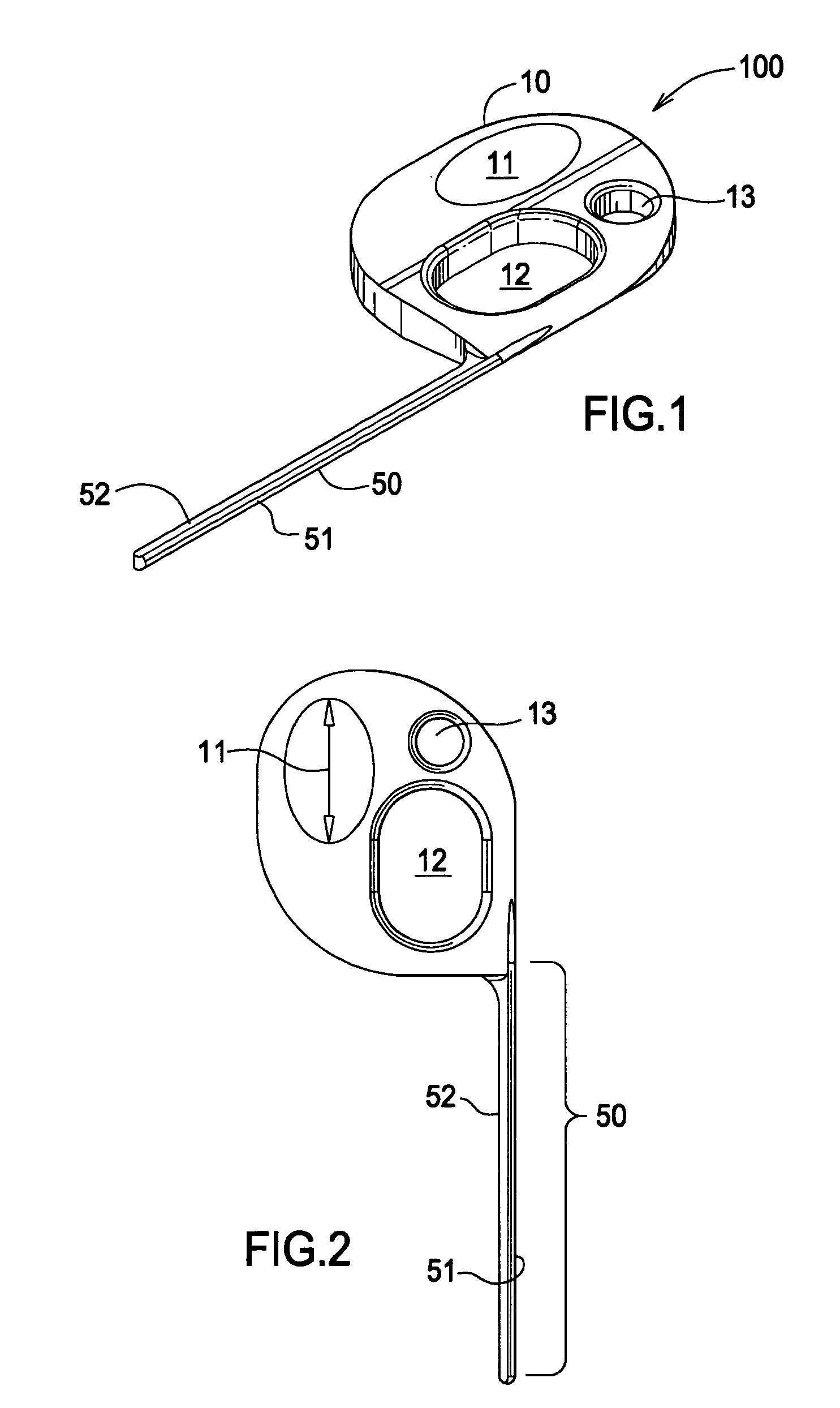
[0019]FIG. 1 is a perspective view of the gauge. The gauge 100 comprises an elongate wear measuring member 50 extending from a body 10. Member 50 comprises an arcuate wear measuring surface 51. Surface 51 typically comprises a semi-cylinder with a square top comprising a flat tactile surface 52. However, surface 51 may comprise in cross-section any geometric form which allows the gauge to contact the sides of a belt groove.

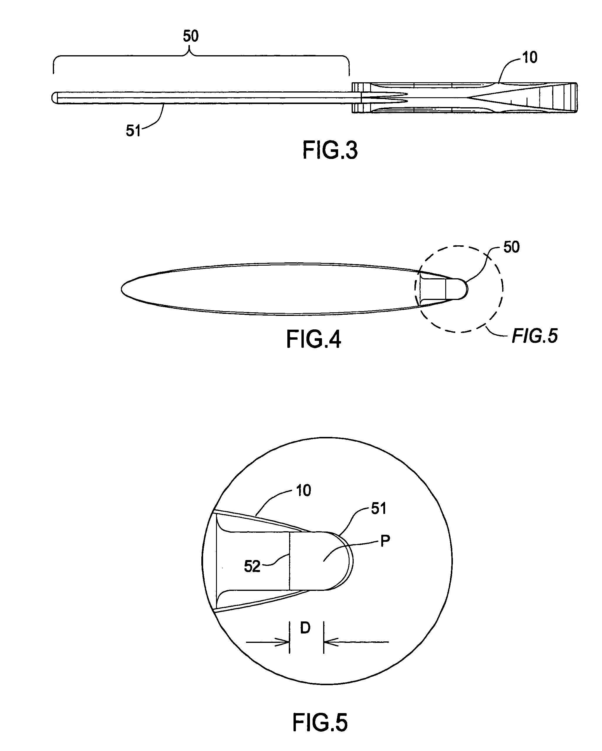
[0020]FIG. 2 is a side view of the gauge. Arcuate surface 51 extends substantially along the entire length of the gauge member 50, see FIG. 5. The form of the arcuate surface 51 is based on the “measuring pin” method of inspecting power transmission pulleys, known in the art. Namely, when placed in a belt groove (G) see FIGS. 6-9, the deeper member 50, and thereby surface 51, drops into a belt groove the more worn the belt.

[0021]FIG. 3 is a bottom view of the gauge. Body 10 is slender in order to facilitate handling and engagement of the gauge with a belt groove. ...


PUM


Abstract

A belt rib wear gauge comprising a body, an elongate member having a length and extending from the body, the elongate member having an arcuate surface, the elongate member further comprising a tactile surface cooperatively disposed with respect to the arcuate surface, and the arcuate surface having a predetermined radial dimension wherein engagement of the elongate member within a belt groove and the position of the tactile surface relative to a datum plane at a tip of belt ribs disposed immediately adjacent to the belt groove indicates a state of wear of the belt ribs.

Description

FIELD OF THE INVENTION[0001]The invention relates to a belt rib wear gauge, and more particularly, to a belt rib wear gauge comprising an arcuate surface having a predetermined radial dimension wherein engagement of the elongate member within a belt groove and the position of the tactile surface relative to a datum plane at a tip of belt ribs disposed immediately adjacent to the belt groove indicates a state of wear of the belt ribs.BACKGROUND OF THE INVENTION[0002]Serpentine drive belts are becoming increasingly durable due to the use of EPDM materials. As a result, a normally reliable indicator of belt wear, cracking, is occurring less frequently although belts are still wearing. Such wear is difficult to visually diagnose and can lead to performance problems in the accessory belt drive system, for example, slipping and noise.[0003]Belt wear in multi-ribbed belts manifests as an increase in belt groove width and depth, which results from wear and reduction in size of the belt ribs...

Claims


Application Information

Patent Timeline
Patent Type & Authority Patents(United States)
IPC IPC(8): G01B5/18
CPCF16G5/20G01B5/18G01B3/46G01B3/28
Inventor SMITH, BENJAMIN MORGANMILLER, DAVID S.VAN OORT, KENT
Owner THE GATES CORP
Why Eureka
Try Eureka