
Upright vacuum cleaner having steering unit

a technology of steering unit and upright vacuum cleaner, which is applied in the direction of suction handle, cleaning filter means, suction cleaner, etc., can solve the problems of deterioration of assemblability, heavy weight of upright vacuum cleaner, and difficulty for users to change the direction of the suction port assembly,

Inactive Publication Date: 2011-05-31
SAMSUNG GWANGJU ELECTRONICS CO LTD
View PDF6 Cites 45 Cited by
  • Summary
  • Abstract
  • Description
  • Claims
  • Application Information

AI Technical Summary

Benefits of technology

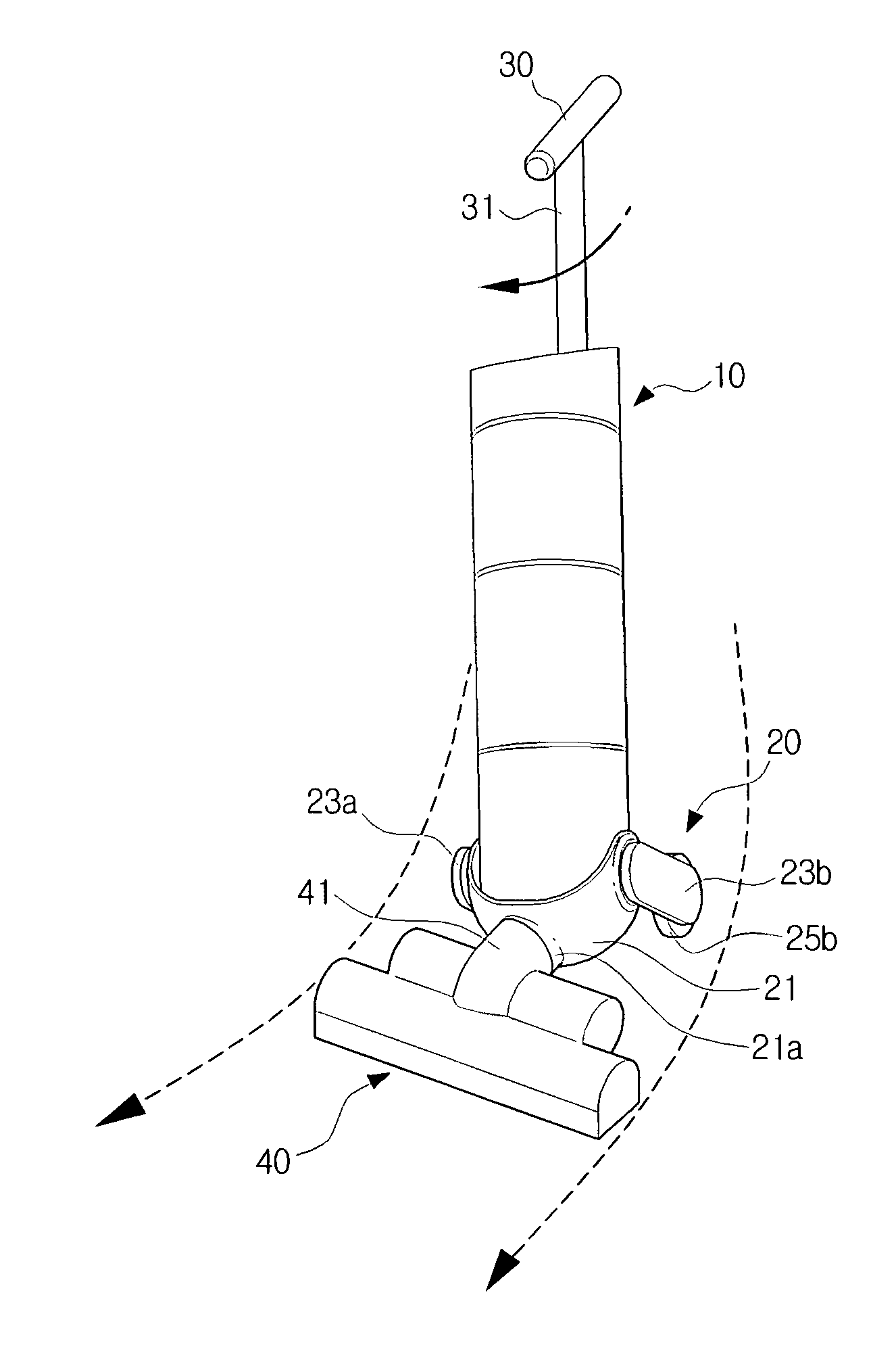
[0010]An aspect of the present disclosure is to address at least the above problems and / or disadvantages and to provide at least the advantages described below. Accordingly, an aspect of the present disclosure is to provide an upright vacuum cleaner having a steering unit to adjust the direction of a suction port assembly conveniently, according to the movement of a center of gravity to the left or right.

Problems solved by technology

An upright vacuum cleaner is generally heavy and thus hard for a user to change the direction of a suction port assembly.
However, the conventional upright vacuum cleaner has a very complicated structure, and accordingly suffers deteriorated assemblability.
Furthermore, a considerable amount of cost and time is required for repair and maintenance.

Method used


Image

  • Upright vacuum cleaner having steering unit
  • Upright vacuum cleaner having steering unit
  • Upright vacuum cleaner having steering unit

Examples


Embodiment Construction

[0023]Hereinafter, a vacuum cleaner for use in both an upright form and a canister form according to exemplary embodiments of the present disclosure will be described in detail with reference to the accompanying drawing figures.

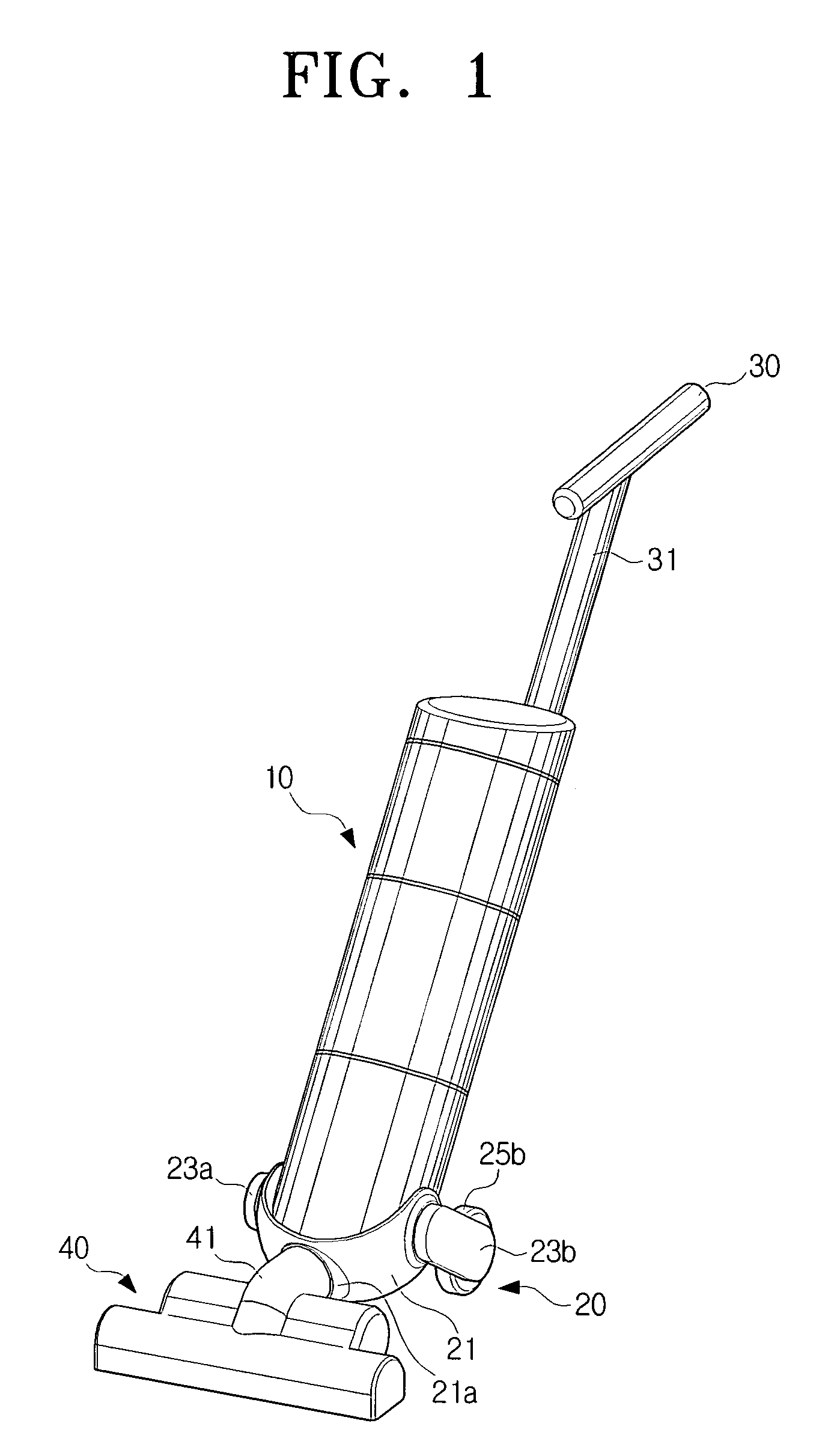
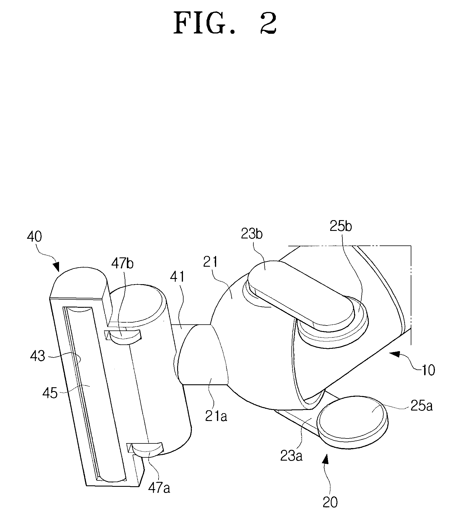
[0024]Referring to FIGS. 1 to 3, an upright vacuum cleaner includes a cleaner body 10, a steering unit 20, a handle 30, and a suction port assembly 40.

[0025]The cleaner body 10 houses therein a suction motor (not shown) as a suction source, and also houses a dust separating and collecting unit (not shown) which has a dust collecting receptacle (not shown) and a dust separating part (not shown).

[0026]The dust separating part (not shown) separates dust from the air drawn by the suction force of a suction motor (not shown) so that the separated dust is collected in the dust collecting receptacle (not shown) disposed therebelow. A cyclone structure may desirably be implemented to separate dust from air by using a centrifugal force. However, this should not be con...


PUM


Abstract

An upright vacuum cleaner having a steering unit is provided. The upright vacuum cleaner includes a cleaner body having a suction motor and a dust separating and collecting unit, a suction port assembly rotatably connected to a lower portion of the cleaner body, a handle mounted to the cleaner body, and a steering unit to elastically support the cleaner body so that the center of gravity of the cleaner body shifts to the direction where the cleaner body is rotated, according to the rotation of the cleaner body to the left or right.

Description

CROSS-REFERENCE TO RELATED APPLICATIONS[0001]This application claims the benefit under 35 U.S.C. § 119(a) of Korean Patent Application No. 10-2007-0101077, filed on Oct. 8, 2007, in the Korean Intellectual Property Office, the entire contents of which are hereby incorporated by reference.BACKGROUND OF THE INVENTION[0002]1. Field of the Invention[0003]The present disclosure relates to a vacuum cleaner. More particularly, the present disclosure relates to an upright vacuum cleaner which draws in dust-laden air from a surface being cleaned, selectively through a suction port assembly or an extension pipe connected to a cleaner body, using a suction force generated by a motor housed in the cleaner body, and which separates the dust from the drawn air.[0004]2. Description of the Related Art[0005]Vacuum cleaners are generally classified into upright vacuum cleaners and canister vacuum cleaners. An upright vacuum cleaner has a suction port assembly which is directly connected to a cleaner ...

Claims


Application Information

Patent Timeline
Patent Type & Authority Patents(United States)
IPC IPC(8): A47L5/00A47L5/28
CPCA47L9/325A47L5/28A47L5/00A47L9/00A47L9/32
Inventor LEE, BYUNG-JOPARK, JOUNG-SOOKIM, TAE-GWANGKIM, SEE-HYUN
Owner SAMSUNG GWANGJU ELECTRONICS CO LTD
Learn More