
Electret electroacoustic transducer

a transducer and electroacoustic technology, applied in the field of electroacoustic transducers, can solve the problems of sound distortion, difficulty in increasing static electricity charges on the diaphragm, etc., and achieve the effect of improving ventilation and increasing the electroacoustic transduction efficiency of the transducer

Inactive Publication Date: 2012-01-05
WU TSUNG HUNG
View PDF39 Cites 10 Cited by
  • Summary
  • Abstract
  • Description
  • Claims
  • Application Information

AI Technical Summary

Benefits of technology

[0014]The embodiment has the adjustment member disposed between the electret vibrating film and the porous complex electrode, so that, a sectional difference is formed between the fixed portion and the adjusted portion of the electret vibrating film. Therefore, it prevents instability of the interaction between the vibrating film and the electrode. Moreover, the adjustment member could control the dynamic characteristic of the vibrating film, adjust the direction of sound and reduce the gap between the electrode and some portion of the vibrating film to increase the transduction efficiency.
[0016]The inner electrostatic protection layer could prevent the touch between the vibrating film and the electrode from affecting the electrostatic charge of the vibrating film. The outer electrostatic protection layer could prevent the outer static electricity from affecting the property of the vibrating film. The film could isolate the outer static electricity and the outer humidity. The through hole could improve the ventilation to increase the electroacoustic transduction efficiency of the transducer when the transducer is disposed in a confinement space of the electronic device.

Problems solved by technology

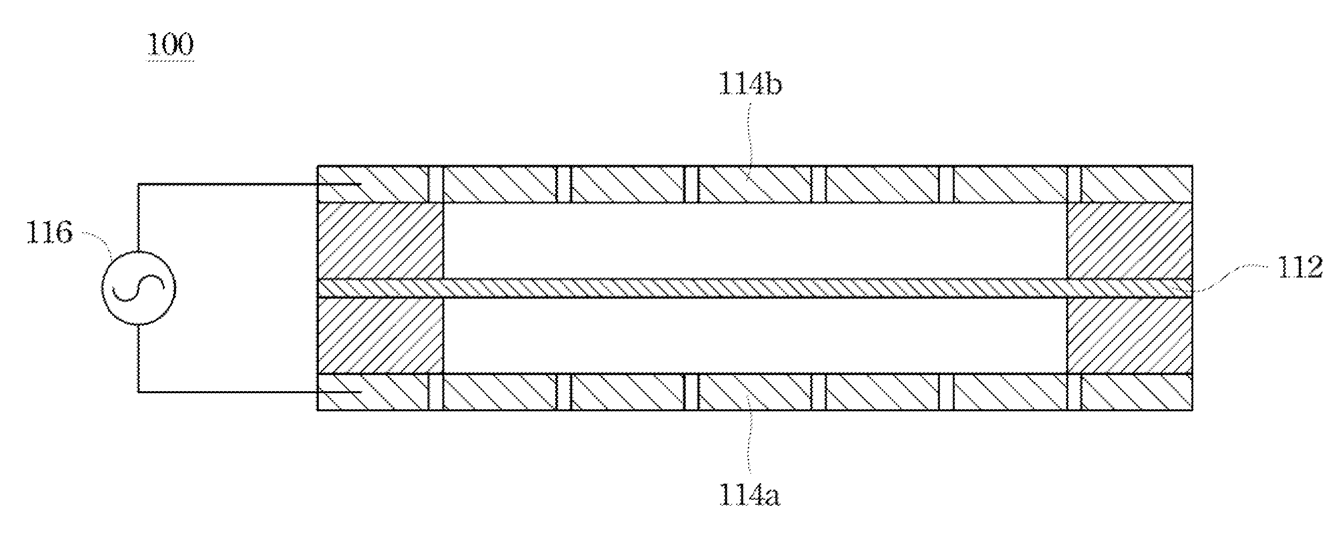
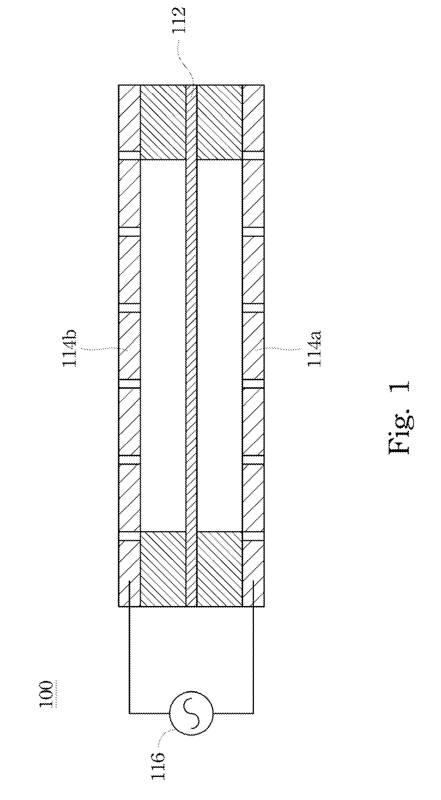
However, due to the material property and the electrical stability, it is difficult to increase the static electricity charges on the diaphragm 112 too much.
Such touch can cause the distortion of sound and reduces the lifetime of the electret electroacoustic transducer 100.
Moreover, the outer static electricity and humidity also affect the charges of the diaphragm and reduce the lifetime and stability of the electret electroacoustic transducer.
However, the confinement space of the electronic device is bad ventilation and reduces the efficiency of the electret electroacoustic transducer as well.

Method used


Image

  • Electret electroacoustic transducer
  • Electret electroacoustic transducer
  • Electret electroacoustic transducer

Examples


Embodiment Construction

[0027]Reference will now be made in detail to the present embodiments of the invention, examples of which are illustrated in the accompanying drawings. Wherever possible, the same reference numbers are used in the drawings and the description to refer to the same or like parts.

[0028]The all embodiments of the present invention could change the size of the adjustment members to adjust the structure between the electret vibrating film, porous complex electrode, and the support member. Therefore, the vibrating property of the vibrating film and the direction of sound could be controlled. The electret vibrating film could be made from fluorine series polymer, such as Fluorinated Ethylene Propylene Copolymer (FEP), Polytetrafluoroethene (PTFE), and Polyvinylidene fluoride (PVDF). Moreover, the electret vibrating film also could be made from other suitable material.

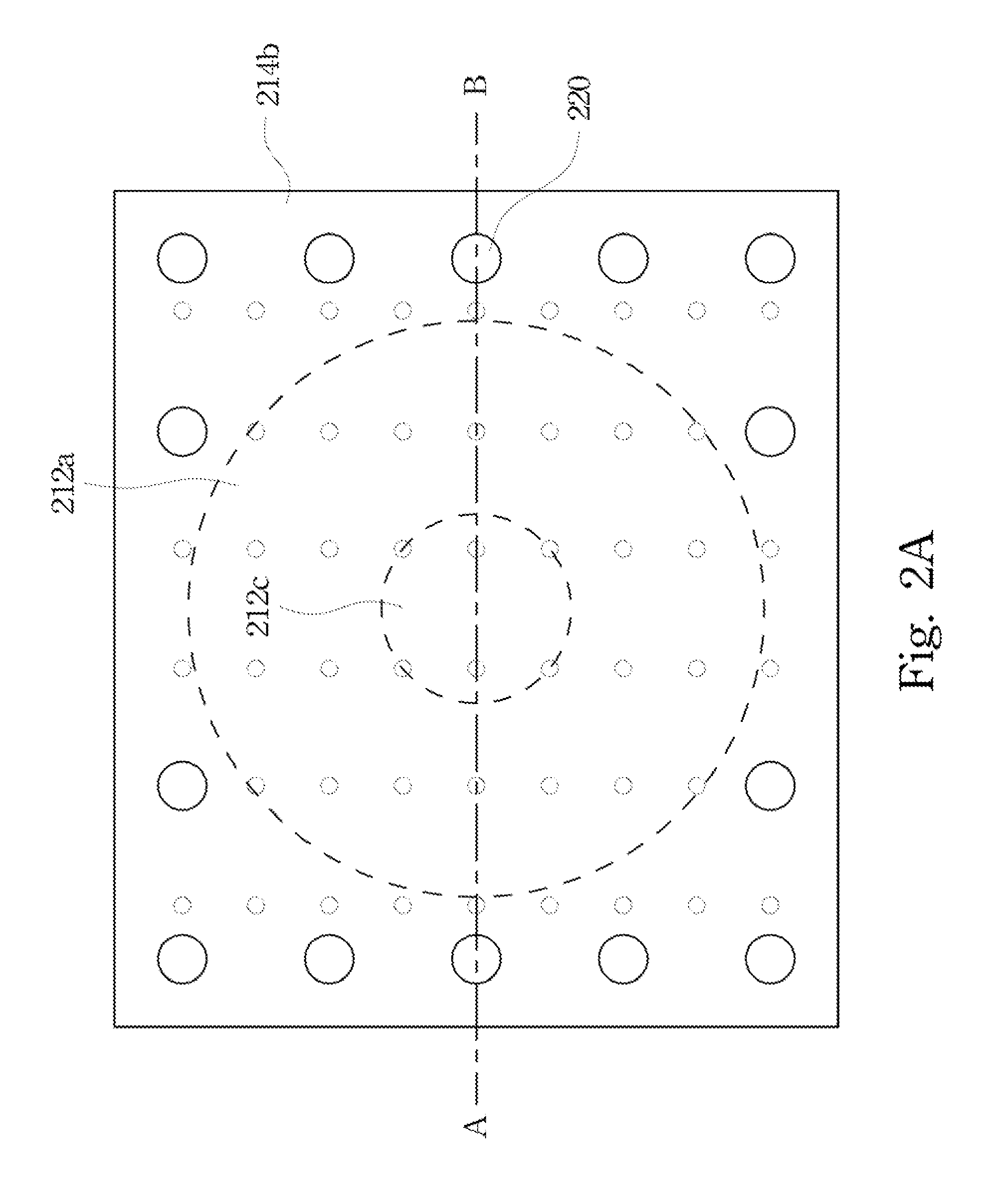
[0029]Please refer to FIG. 2A and FIG. 2B together. FIG. 2A is a schematic diagram of a top view of the electret electroacous...


PUM


Abstract

An electret electroacoustic transducer comprises first porous complex electrode, support member, electret vibrating film and first adjustment member. Support member is configured on the first porous complex electrode. The fixed portion of the electret vibrating film is fixed on the support member. Adjustment member is set between the first porous complex electrode and the electret vibrating film. A sectional difference is formed between the fixed portion and the adjusted portion of the electret vibrating film.

Description

RELATED APPLICATIONS[0001]This application claims priority to Taiwan Application Serial Number 99212462, filed Jun. 30, 2010, which is herein incorporated by reference.BACKGROUND[0002]1. Field of Invention[0003]The present invention relates to an electroacoustic transducer. More particularly, the present invention relates to an electret electroacoustic transducer.[0004]2. Description of Related Art[0005]Please refer to FIG. 1. FIG. 1 is a schematic diagram of a sectional view of a conventional electret electroacoustic transducer. The conventional electret electroacoustic transducer 100 which is an acoustical device based on the Coulomb's Law. The Coulomb's Law is a law describing two objects induced push-pull effect when two objects have same or opposite electric properties at the same time. The diaphragm 112 composed of electret material is disposed between the electrodes 114a, 114b. The alternating signal source 116 is connected to the electrodes 114a, 114b. Therefore, the alterna...

Claims


Application Information

Patent Timeline
Patent Type & Authority Applications(United States)
IPC IPC(8): H04R25/00
CPCH04R19/01
Inventor WU, TSUNG-HUNGLIOU, ZHI-YUAN
Owner WU TSUNG HUNG
Learn More