Electrical fixture for outdoor umbrella

an outdoor umbrella and electric technology, applied in the field of outdoor umbrellas, can solve the problems of damage to the main body of the outdoor umbrella, the mounting arrangement cannot be attached to the outdoor umbrella, and the wear and tear of the screw and the tapped holes is easy to occur, so as to achieve the effect of secure and stable way

Inactive Publication Date: 2010-02-04
LI WANDA YING
View PDF11 Cites 10 Cited by
  • Summary
  • Abstract
  • Description
  • Claims
  • Application Information

AI Technical Summary

Benefits of technology

[0010]A main object of the present invention is to provide an electric fixture for an outdoor umbrella, wherein the electric fixture comprises a shaft supporter and a utility housing adapted for providing a secure attachment on the shaft and a stable support to the housing. Therefore, it provides a secure and stable way to attach an additional add-on electrical fixture for the conventional outdoor umbrella such that the user is able to securely mounting the electric apparatus at the outdoor umbrella.

Problems solved by technology

However, such a mounting arrangement has several drawbacks.
In other words, if the size between the tapped hole and the screw doesn't match, the mounting arrangement can't be attached on the outdoor umbrella.
To make matters worse, with constant use, the screw and the tapped holes can wear and tear very easily.
It not only causes damages to the main body of the outdoor umbrella, but also reduces the stability of the outdoor umbrella.
In addition, sometimes the audio system or the illuminator is really heavy.
Therefore, mounting the mounting arrangement with the electrical apparatus on the outdoors umbrella is a challenging task.
Other problems arise from the uneven weight distribution when the heavy electrical apparatus makes the whole outdoor umbrella unstable.
For example, in the unstable situation, the strong wind may blow the outdoor umbrella down.
Therefore, the user is not able to adjust a mounting position of the shaft supporter for their practical use.
Moreover, because all the screw holes are fixed, the mounting arrangement is only allowable to put the restricted area.
Furthermore, if the user tries to adjust the mounting position, a screw-driver is required.
It is a hassle for people always carry the screw driver themselves.

Method used


Image

  • Electrical fixture for outdoor umbrella
  • Electrical fixture for outdoor umbrella
  • Electrical fixture for outdoor umbrella

Examples


Embodiment Construction

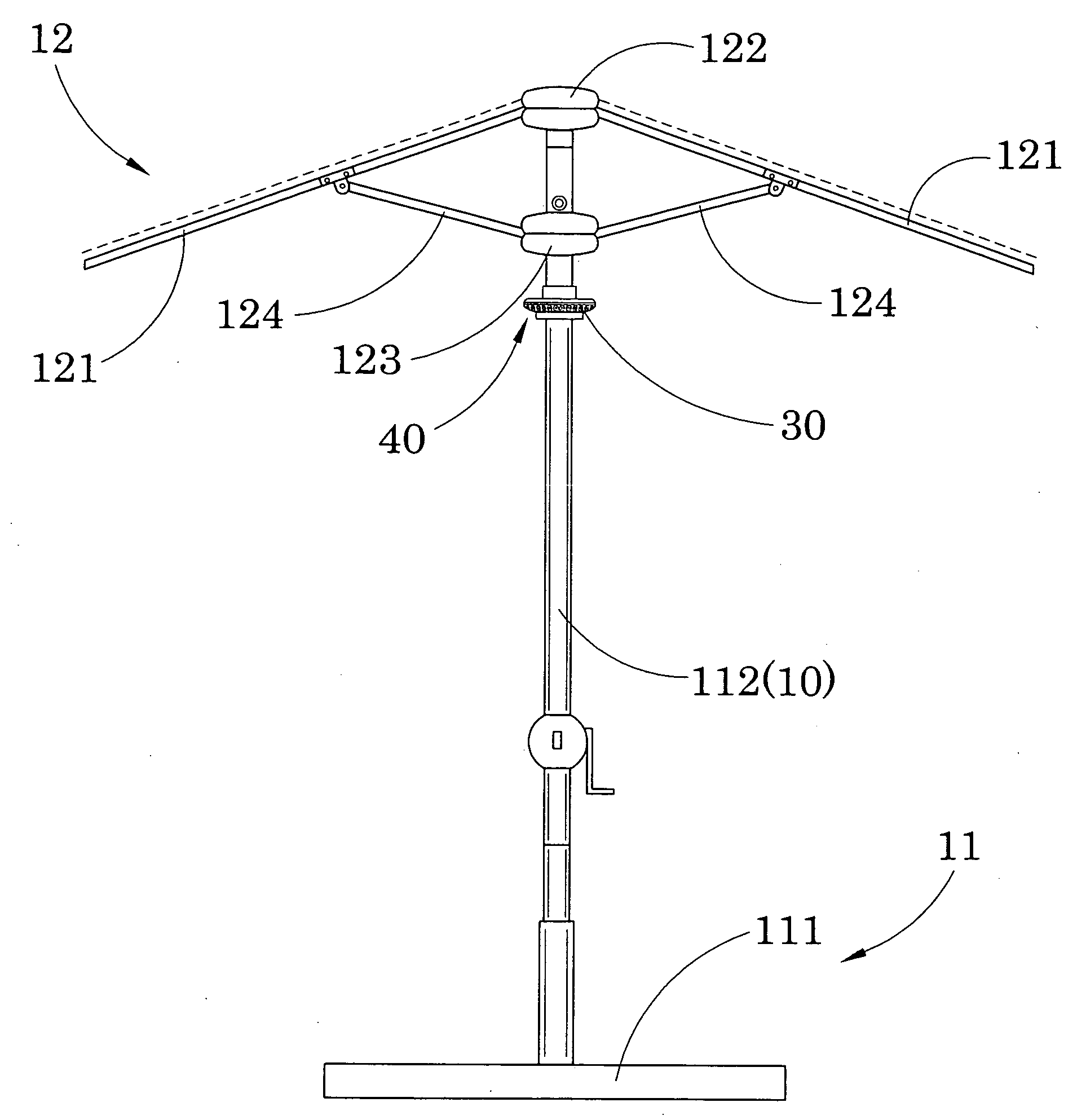
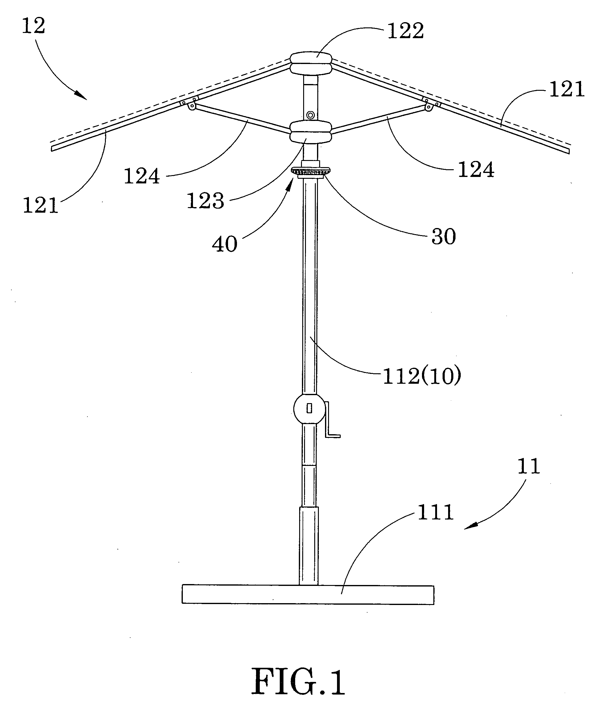
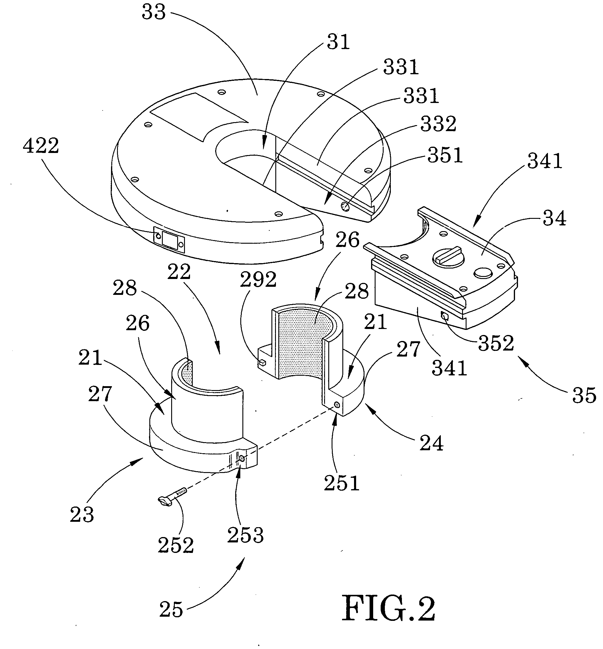
[0029]Referring to FIGS. 1 and 2 of the drawing, an electrical fixture for an outdoor umbrella is illustrated, wherein the electrical fixture is adapted for mounting at the outdoor umbrella having an elongated shaft 10, comprises a shaft supporter 20, a utility housing 30, and an electrical apparatus 40.

[0030]The outdoor umbrella, such as a conventional outdoor umbrella, comprises a supporting frame 11 and an awning frame 12 suspendedly supported by the supporting frame 11 to support an awning element and to define a shading area under the awning element, wherein the awning frame 12 is adapted to fold between an opened position and a closed position.

[0031]The supporting frame 11 comprises a ground stand 111 and a supporting shaft 112 is upwardly extended from the ground stand 111 to support the awning frame 12. The awning frame 12 comprises a plurality of awning arms 121 radially and pivotally extended from the upper housing 122 to support the awning element, and a plurality of fold...


PUM


Abstract

An electrical fixture for an outdoor umbrella having a shaft includes a shaft supporter adapted for securely mounting at elongated shaft of the outdoor umbrella, a utility housing having a through slot engaging with the shaft supporter at a position the utility housing is supportively sat at the seating platform of the shaft supporter for suspendedly supporting the utility housing at the elongated shaft of the outdoor umbrella, and an electrical apparatus received in the utility housing for providing an added-on function of outdoor umbrella.

Description

BACKGROUND OF THE PRESENT INVENTION[0001]1. Field of Invention[0002]The present invention relates to an outdoor umbrella, and more particularly to an electric fixture for an outdoor umbrella, wherein the electric fixture comprises a shaft supporter and a utility housing adapted for providing a secure attachment on the shaft and a stable support to the housing such that the user is able to securely mount the additional add-on electrical apparatus at the outdoor umbrella.[0003]2. Description of Related Arts[0004]A conventional outdoor umbrella is usually composed of an umbrella frame which comprises a supporting frame and an awning frame movably supported on the supporting frame, and an awning fabric supported on the awning frame for providing shade under the awning fabric. Conventionally, the outdoor umbrella is usually foldable so that when it is not in use, the outdoor umbrella can be folded into a compact size for convenient transport and storage.[0005]People usually use the conve...

Claims


Application Information

Patent Timeline
Patent Type & Authority Applications(United States)
IPC IPC(8): A45B25/00A45B3/02
CPCA45B3/04A45B2025/003A45B2023/0012A45B25/00
Inventor LI, WANDA YING
Owner LI WANDA YING
Why Eureka
Try Eureka