Method for adjusting illumination direction angle of strobe device, strobe device, and imaging device equipped with strobe device

a technology of illumination direction angle and strobe device, which is applied in the direction of color television details, television systems, instruments, etc., can solve the problems of reducing operability or workability, and the photographer cannot take a photograph with good timing, and achieve excellent operability and workability, good timing

Inactive Publication Date: 2015-02-05
PANASONIC INTELLECTUAL PROPERTY MANAGEMENT CO LTD
View PDF4 Cites 10 Cited by
  • Summary
  • Abstract
  • Description
  • Claims
  • Application Information

AI Technical Summary

Benefits of technology

[0018]With this configuration, the second signal is transmitted to the other strobe device, and thereby the illumination direction angle of the other strobe device is changed to the desired illumination direction angle. As a result, the illumination direction angle of the other strobe device can be remotely adjusted in the position of the self strobe device. Alternatively, the second signal is transmitted from the other strobe device, and thereby the illumin

Problems solved by technology

As a result, the operability or workability is reduced and

Method used


Image

  • Method for adjusting illumination direction angle of strobe device, strobe device, and imaging device equipped with strobe device
  • Method for adjusting illumination direction angle of strobe device, strobe device, and imaging device equipped with strobe device
  • Method for adjusting illumination direction angle of strobe device, strobe device, and imaging device equipped with strobe device

Examples


Embodiment Construction

[0030]Hereinafter, a description is provided for a method for adjusting the illumination direction angle of a strobe device, the strobe device, and an imaging device equipped with the strobe device in accordance with an exemplary embodiment of the present invention, with reference to the accompanying drawings. The exemplary embodiment to be described below is an example where the present invention is embodied, and does not limit the technical scope of the present invention.

Exemplary Embodiment

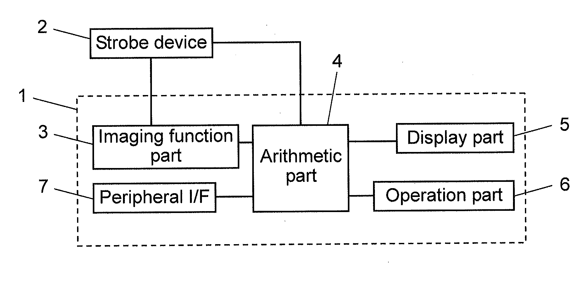
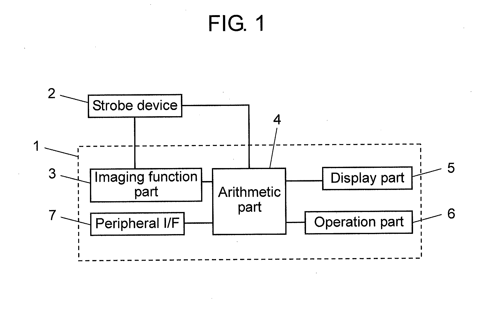
[0031]Hereinafter, a description is provided for a strobe device and an imaging device equipped with the strobe device in accordance with the exemplary embodiment of the present invention, with reference to FIG. 1 through FIG. 5.

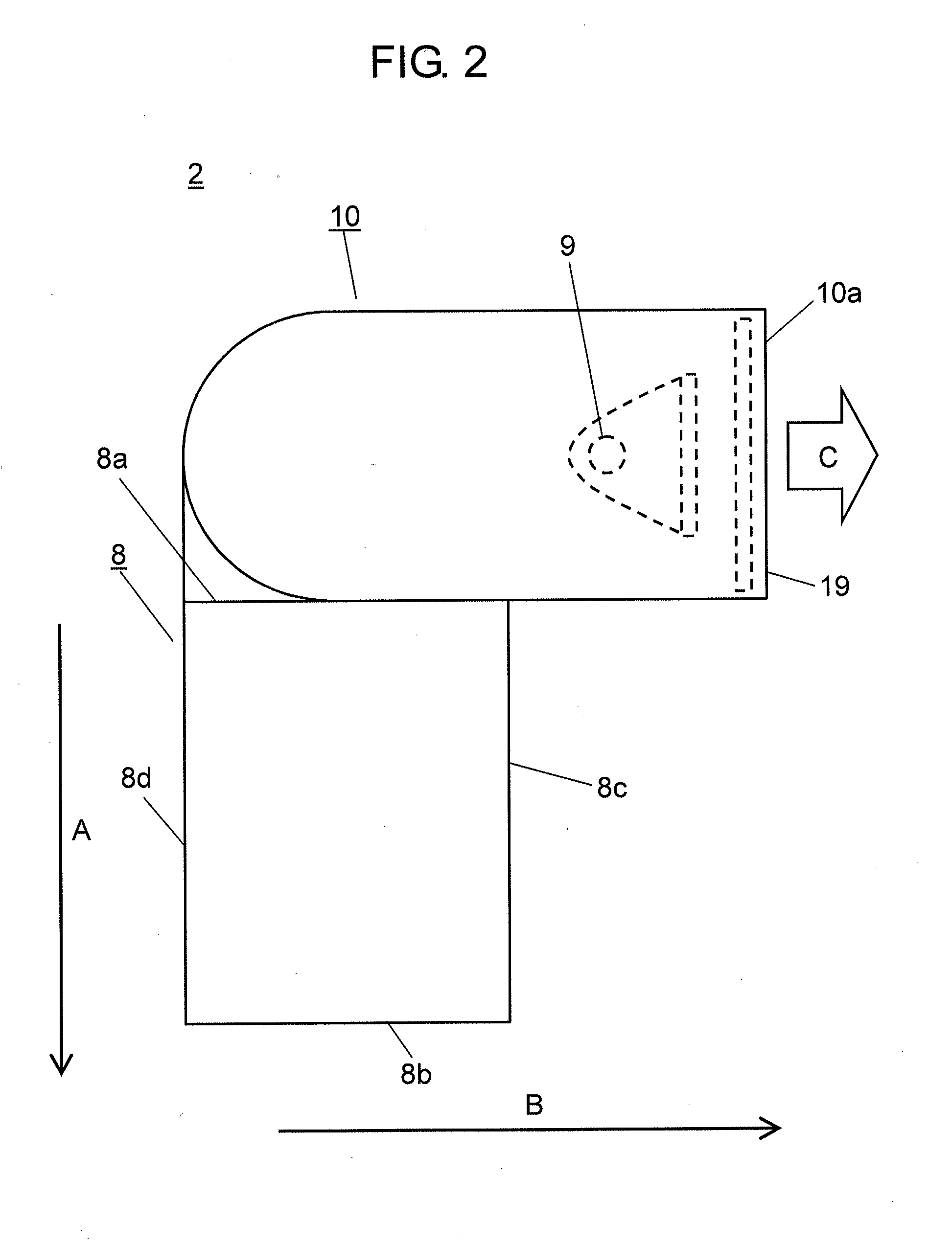
[0032]FIG. 1 is a block diagram showing a configuration of an imaging device in accordance with the exemplary embodiment of the present invention. FIG. 2 is a side view of a strobe device in accordance with the exemplary embodiment. FIG. 3 is a top view of the strobe de...


PUM


Abstract

A method for adjusting the illumination direction angle of a strobe device includes the steps of: transmitting to a specific strobe device, a first signal related to the present illumination direction angle of the strobe device being adjusted; based on the first signal, causing the illumination direction angle of the specific strobe device to correspond to the illumination direction angle of the strobe device being adjusted; changing the illumination direction angle of the specific strobe device to a state desirable for the strobe device being adjusted; transmitting, to the strobe device being adjusted, the amount of further change in the illumination direction angle of the specific strobe device, as a second signal; and changing the illumination direction angle of the strobe device being adjusted, based on the second signal. With this method, the illumination direction angle of the strobe device can be remotely adjusted.

Description

[0001]This application is a U.S. National Phase Application of PCT International Application PCT / JP2013 / 002428.TECHNICAL FIELD[0002]The present invention relates to a method for adjusting the illumination direction angle of a strobe device, the strobe device, and an imaging device equipped with the strobe device in stroboscopic photography using a plurality of strobe devices.BACKGROUND ART[0003]Conventionally, stroboscopic photography in which an object is photographed using a plurality of strobe devices has been performed (see Patent Literature 1, for example). At this time, each of the strobe devices is disposed in the position suitable for the object, e.g. on the front side, rear side, vertical side, and horizontal side of the object.[0004]However, in stroboscopic photography using a plurality of strobe devices, the photographer needs to adjust the illumination direction angle of each strobe device. Thus, the photographer needs to move to the proximity of the strobe device to be ...

Claims


Application Information

Patent Timeline
IPC IPC(8): H04N5/225H04N5/235
CPCH04N5/2354H04N5/2256G03B15/05G03B2215/0521G03B2215/0557G03B2215/0585H04N23/56H04N23/74
Inventor UMEHARA, TAKASHIOOYAMA, KAZUHIKOKAWABATA, KATSUNORI
Owner PANASONIC INTELLECTUAL PROPERTY MANAGEMENT CO LTD
Why Eureka
Try Eureka