Castor that is braked and positioned simultaneously

a technology of brakes and castors, applied in the field of castors, can solve problems such as inconvenience for users, and achieve the effect of enhancing the locking effect of the castors

Active Publication Date: 2011-05-31
SUNNY CASTORS
View PDF9 Cites 26 Cited by
  • Summary
  • Abstract
  • Description
  • Claims
  • Application Information

AI Technical Summary

Benefits of technology

[0007]A further objective of the present invention is to provide a castor, wherein when the wheel unit is locked onto the castor body, the castor body is locked onto the suspension unit simultaneously so that the castor body will not be rotatable relative to the suspension unit when the wheel unit is locked onto the castor body to prevent the wheel unit from slipping freely, thereby enhancing the locking effect of the castor.

Problems solved by technology

However, the castor body is rotatable relative to the fixing bolt when each of the rollers of the wheel unit is locked onto the castor body, so that the wheel unit easily slips due to rotation the castor body relative to the fixing bolt, thereby causing inconvenience to a user.

Method used


Image

  • Castor that is braked and positioned simultaneously
  • Castor that is braked and positioned simultaneously
  • Castor that is braked and positioned simultaneously

Examples


Embodiment Construction

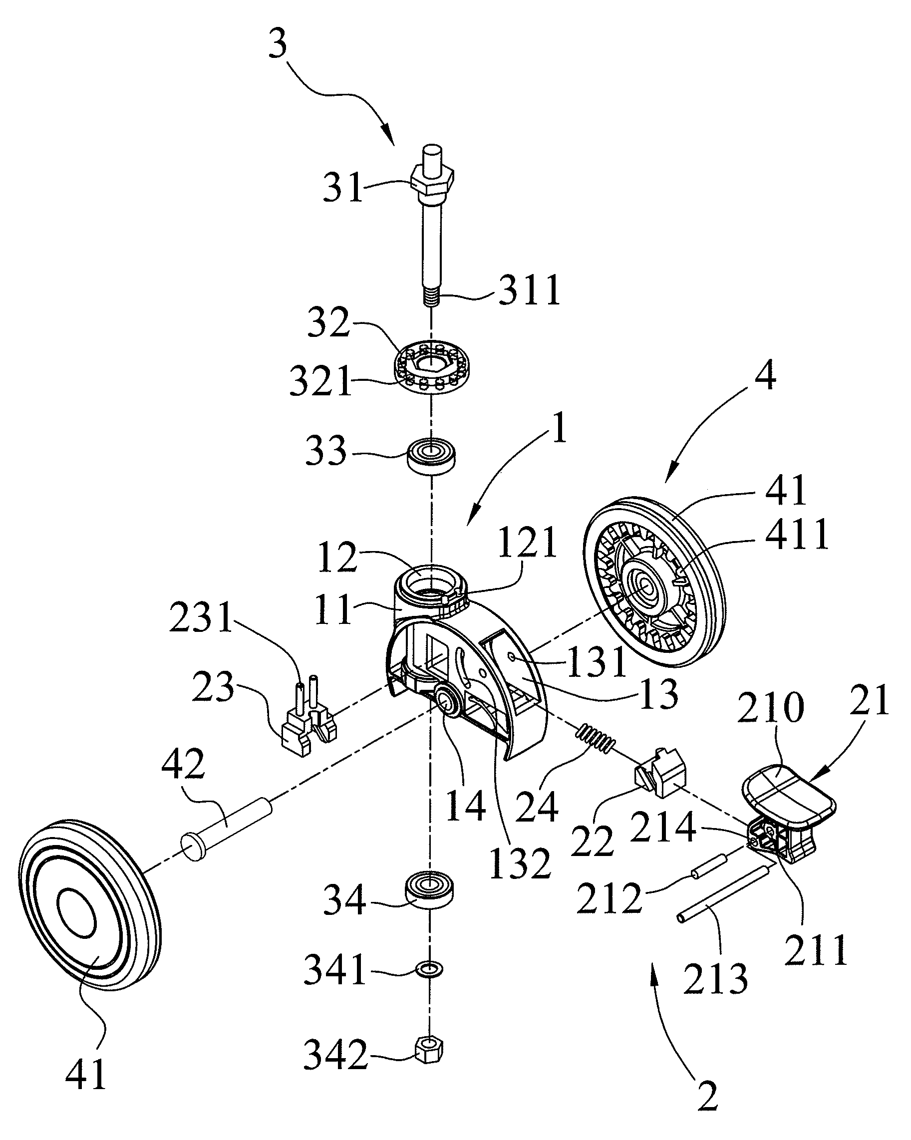
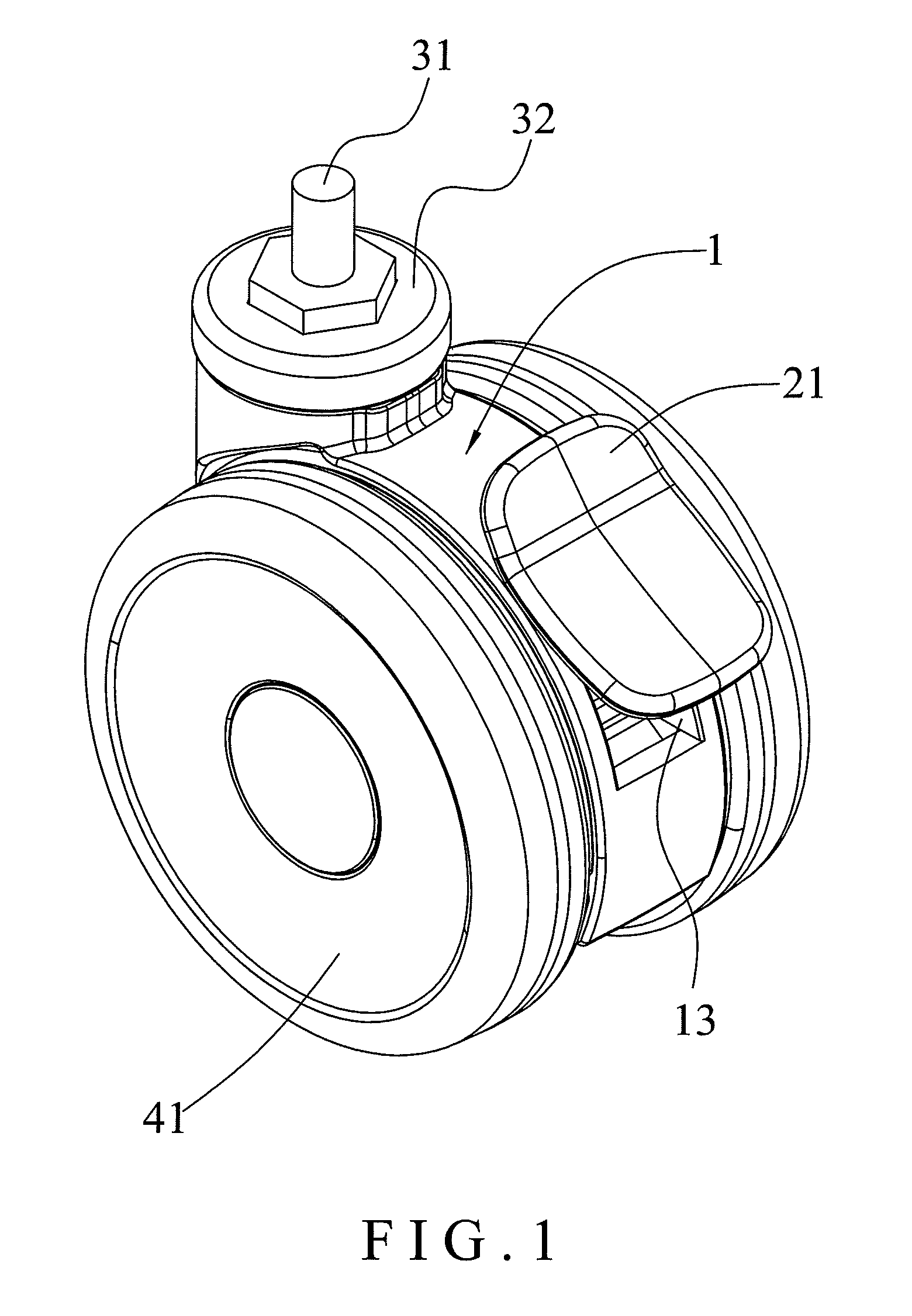
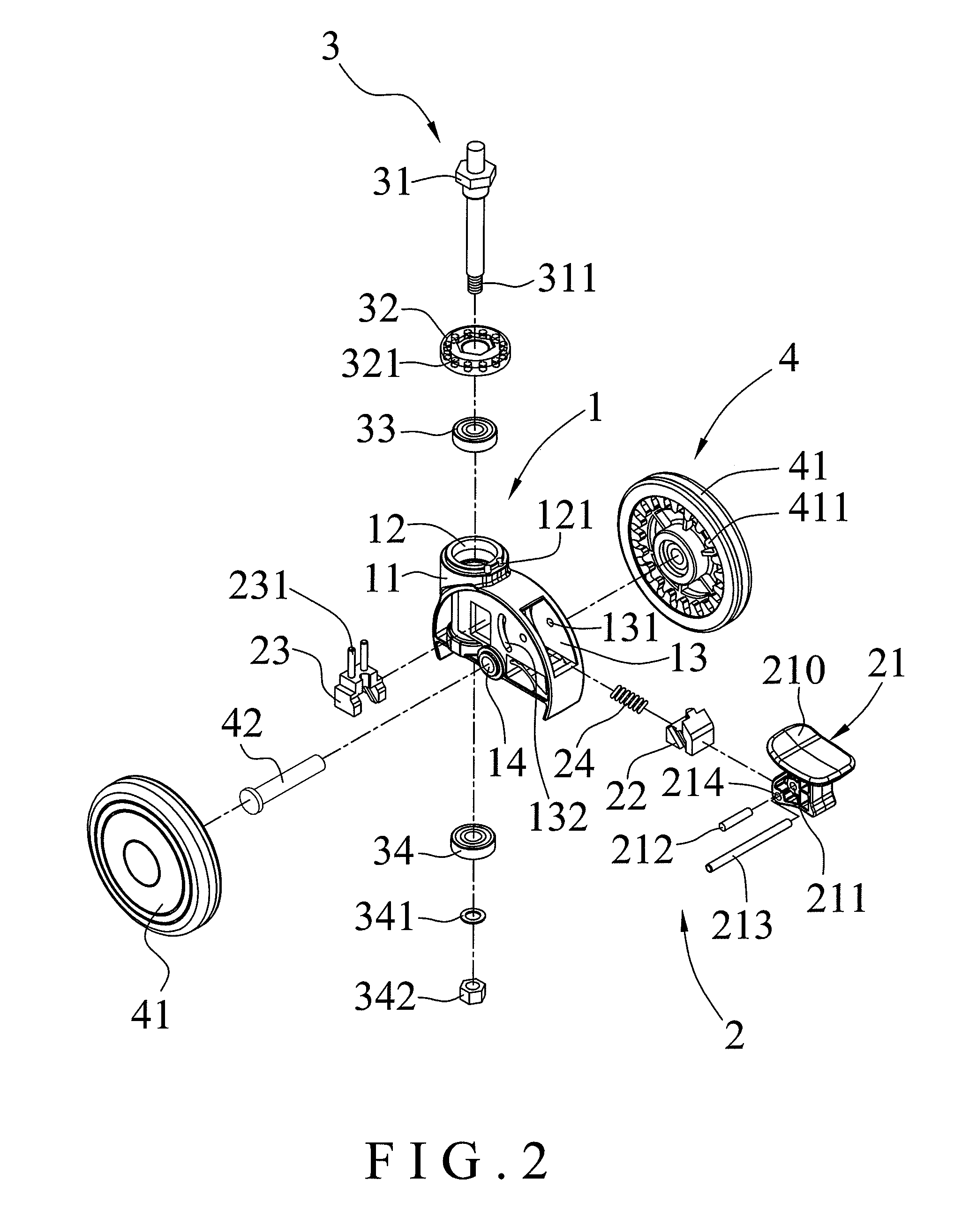
[0019]Referring to the drawings and initially to FIGS. 1-7, a castor in accordance with the preferred embodiment of the present invention comprises a suspension unit 3, a castor body 1, a wheel unit 4, and a brake unit 2.

[0020]The suspension unit 3 includes an upright fixing bolt 31 and a locking member 32 secured on the fixing bolt 31. The locking member 32 of the suspension unit 3 has a bottom formed with a plurality of locking holes 321. The castor body 1 is rotatably mounted on the fixing bolt 31 of the suspension unit 3. The wheel unit 4 includes two rollers 41 each rotatably mounted on the castor body 1 and each having a side formed with a plurality of locking grooves 411.

[0021]The brake unit 2 includes a positioning block 23 movably mounted in the castor body 1 and movable to press the locking member 32 of the suspension unit 3 to lock the castor body 1 onto the locking member 32 of the suspension unit 3, a sliding block 22 movably mounted in the castor body 1 and combined wi...


PUM


Abstract

A castor includes a suspension unit, a castor body, a wheel unit, and a brake unit. The suspension unit includes an upright fixing bolt and a locking member. The wheel unit includes two rollers. The brake unit includes a positioning block, a sliding block, a biasing member, a drive member, and a braking pin. Thus, when the drive member of the brake unit is pressed, each of the rollers of the wheel unit is braked by and locked onto the castor body, and the castor body is locked onto the fixing bolt simultaneously, thereby locking the castor exactly and stably.

Description

BACKGROUND OF THE INVENTION[0001]1. Field of the Invention[0002]The present invention relates to a castor and, more particularly, to a castor for a chair, hand cart, sick bed and the like.[0003]2. Description of the Related Art[0004]A chair comprises a stand and a plurality of castors mounted on the bottom of the stand. A conventional chair castor comprises an upright fixing bolt mounted on the bottom of the stand of the chair, a castor body rotatably mounted on the fixing bolt, a wheel unit including two rollers each rotatably mounted on the castor body and each having a periphery formed with a plurality of locking grooves, and a brake unit including a pressing member pivotally mounted on the castor body and provided with a braking member that is movable into one of the locking grooves of each of the rollers of the wheel unit to lock each of the rollers of the wheel unit onto the castor body. Thus, when the pressing member of the brake unit is pressed, the braking member is movable...

Claims


Application Information

Patent Timeline
Patent Type & Authority Patents(United States)
IPC IPC(8): A47B91/00
CPCB60B33/0021B60B33/0028B60B33/0042B60B33/0049B60B33/0057B60B33/0073B60B33/0086B60B33/021B60B33/025B60B33/0068Y10T16/1853Y10T16/195
Inventor YANG, SUNG-WANGLIN, MING-HSIENCHEN, PO-LU
Owner SUNNY CASTORS
Why Eureka
Try Eureka