Ceramic matrix composite turbine engine components with unitary stiffening frame

a composite material and turbine engine technology, applied in the direction of machines/engines, stators, liquid fuel engines, etc., can solve the problems of increasing the number of natural limitations and manufacturing constraints of cmc materials, reducing the interlaminar tensile strength of materials, and complicated active cooling systems

Inactive Publication Date: 2011-05-31
SIEMENS ENERGY INC
View PDF31 Cites 78 Cited by
  • Summary
  • Abstract
  • Description
  • Claims
  • Application Information

AI Technical Summary

Problems solved by technology

Such active cooling systems are usually complicated and costly.
However, there are a number of natural limitations and manufacturing constraints associated with CMC materials.
In addition, anisotropic shrinkage of the matrix and the fibers can result in de-lamination defects, particularly in small radius corners and tightly-curved sections, which can further reduce the interlaminar tensile strength of the material.
Such areas tend to be design-limiting features of these components.

Method used


Image

  • Ceramic matrix composite turbine engine components with unitary stiffening frame
  • Ceramic matrix composite turbine engine components with unitary stiffening frame
  • Ceramic matrix composite turbine engine components with unitary stiffening frame

Examples


Embodiment Construction

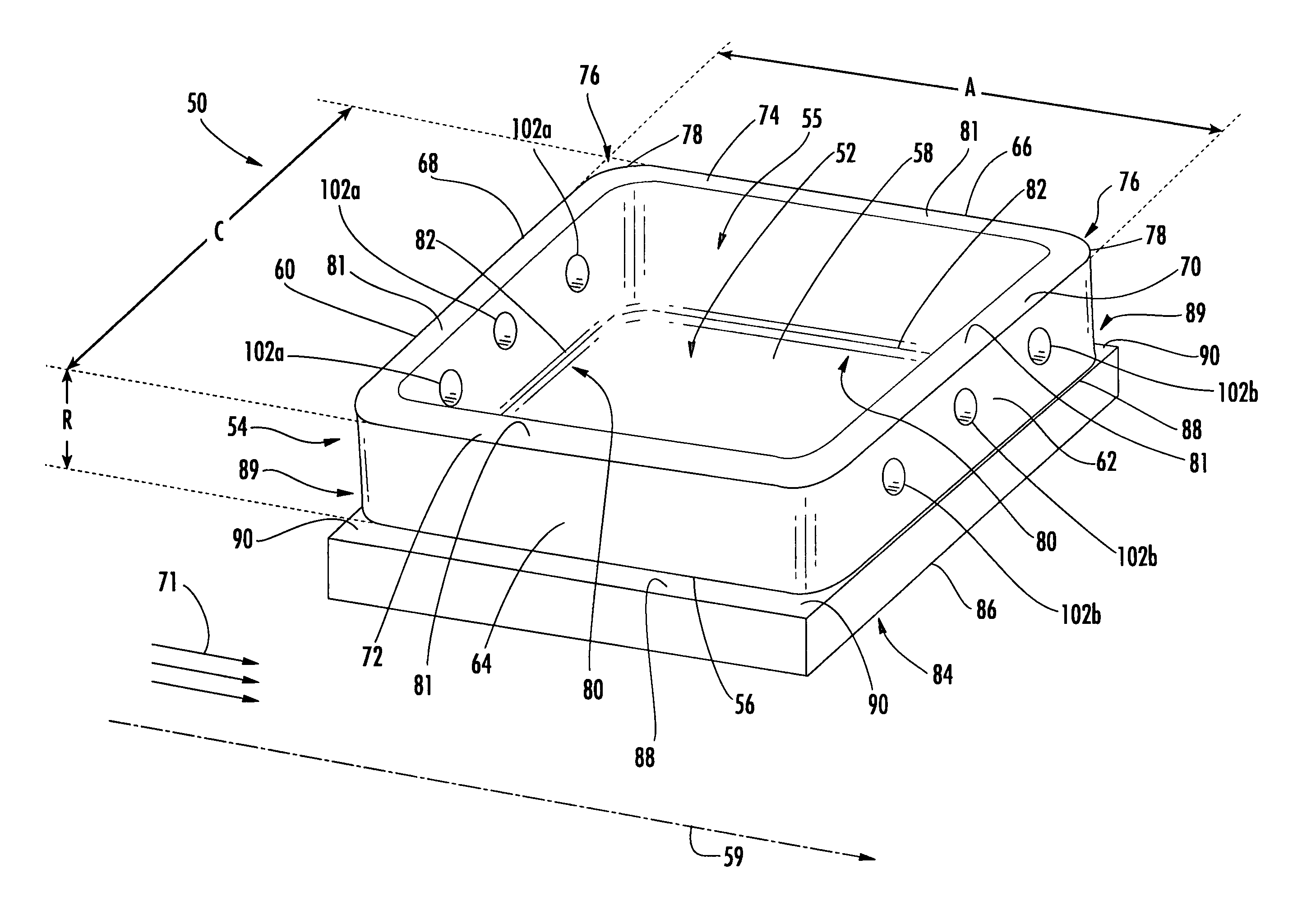
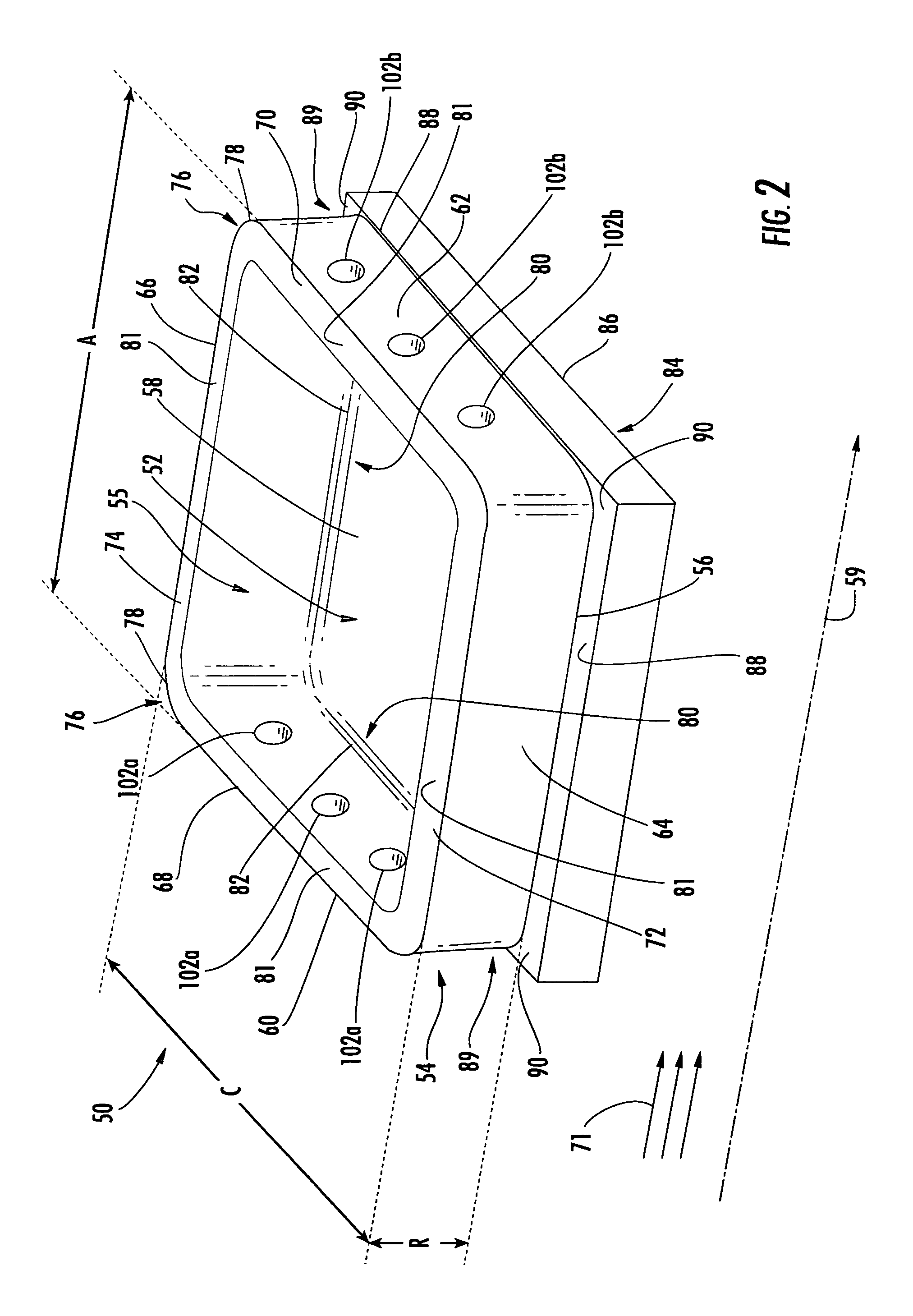
[0029]Embodiments of the invention are directed to a construction for a ceramic matrix composite turbine engine component. Aspects of the invention will be explained in connection with a ring seal segment, but the detailed description is intended only as exemplary. An embodiment of the invention is shown in FIGS. 2-10, but the present invention is not limited to the illustrated structure or application.

[0030]FIG. 2 shows a ring seal segment 50 according to aspects of the invention. The ring seal segment 50 can include a base portion 52 and a frame portion 54 having at least three side walls. According to aspects of the invention, the ring seal segment 50 is a unitary construction. That is, the base portion 52 and the frame portion 54 are a single piece. More particularly, the side walls of the frame portion 54 are formed together as a single piece, and the side walls are formed together as a single piece with the base portion 52. A ring seal segment 50 according to aspects of the in...


PUM

PropertyMeasurementUnit
anglesaaaaaaaaaa
thermal insulatingaaaaaaaaaa
temperatureaaaaaaaaaa

Abstract

Aspects of the invention are directed to a ring seal segment having a base portion and a frame portion. The base portion and the frame portion are a unitary structure. The frame portion is made of four unitary side walls: a forward wall, an aft wall and a pair of transverse side walls. The side walls can be arranged in a rectangular configuration. At least a part of the base portion can be coated with a thermal insulating material. A ring seal segment according to aspects of the invention is well suited to withstand the expected operational loads in the turbine section. The transverse side walls can provide bending strength to the base and can strengthen the forward and aft side walls. Transition regions between the side walls and the base portion are strengthened by three perpendicular planes that cooperate to provide structural strength to the ring seal segment.

Description

FIELD OF THE INVENTION[0001]Aspects of the invention relate in general to turbine engines and, more particularly, to ceramic matrix composite components of a turbine engine.BACKGROUND OF THE INVENTION[0002]FIG. 1 shows an example of one known turbine engine 10 having a compressor section 12, a combustor section 14 and a turbine section 16. In the turbine section 16, there are alternating rows of stationary airfoils 18 (commonly referred to as vanes) and rotating airfoils 20 (commonly referred to as blades). Each row of blades 20 is formed by a plurality of airfoils 20 attached to a disc 22 provided on a rotor 24. The blades 20 can extend radially outward from the discs 22 and terminate in a region known as the blade tip 26. Each row of vanes 18 is formed by attaching a plurality of vanes 18 to a vane carrier 28. The vanes 18 can extend radially inward from the inner peripheral surface 30 of the vane carrier 28. The vane carrier 28 is attached to an outer casing 32, which encloses th...

Claims


Application Information

Patent Timeline
Patent Type & Authority Patents(United States)
IPC IPC(8): F02C1/00F02G3/00
CPCF01D11/122F05D2250/12F05D2300/603F05D2250/121F05D2300/21F05D2240/11
Inventor RADONOVICH, DAVID CHARLESKELLER, DOUGLAS ALLENMORRISON, JAY ALANGONZALEZ, MALBERTO FERNANDEZSCHIAVO, ANTHONY L.
Owner SIEMENS ENERGY INC
Why Eureka
Try Eureka